メーカー品番 SC1631
RASPBERRY PI PICO 2 RP2350
Raspberry Pi
Microcontrollers LEDs / Discrete / Modules Environmental Temperature Switches Pushbutton Wire Jumper Wires Breadboards Raspberry Pi MCU
Interrupts are a fundamental mechanism in embedded systems that allow the processor to temporarily pause normal program execution to handle time-critical events, then automatically resume where it left off. Without interrupts, programs would need to constantly poll (repeatedly check) hardware peripherals to detect events like button presses, timer expirations, or incoming serial data. This is often a wasteful approach that keeps the processor busy and prevents it from sleeping to save power. Interrupts solve this by letting hardware signal the processor when something important happens, allowing your main program to do other work or enter low-power sleep modes until an event requires attention.
In this tutorial, we'll explore how to configure and handle timer interrupts on the Raspberry Pi Pico 2, creating a blinking LED program where the processor spends most of its time sleeping while hardware interrupts handle all the timing. This interrupt-driven approach is more efficient than our original polling-based blinky demo and introduces patterns you'll use throughout embedded development.
Note that all code for this series can be found in this GitHub repository.
When an interrupt occurs, the processor immediately suspends execution of the current code, saves its state (like register values and the program counter), and jumps to a special function called an interrupt service routine (ISR) or interrupt handler. The ISR executes quickly to handle the event (like toggling a pin, clearing a flag, or scheduling the next timer alarm), then returns control to the main program, which resumes exactly where it was interrupted.
Interrupts can come from various sources: external interrupts trigger when GPIO pins change state (like a button press or sensor signal), while internal interrupts come from on-chip peripherals like timers, UART receivers, ADC conversions completing, or DMA transfers finishing. Each interrupt source has a priority level, and the Nested Vectored Interrupt Controller (NVIC) in ARM Cortex-M processors manages which interrupts can preempt others.
For our timer interrupt example, we'll configure a timer alarm to fire every 500 milliseconds, triggering an interrupt that toggles an LED. We’ll do this while the main program simply sleeps using the wfi() (wait for interrupt) instruction, demonstrating how interrupts enable responsive, power-efficient embedded applications.
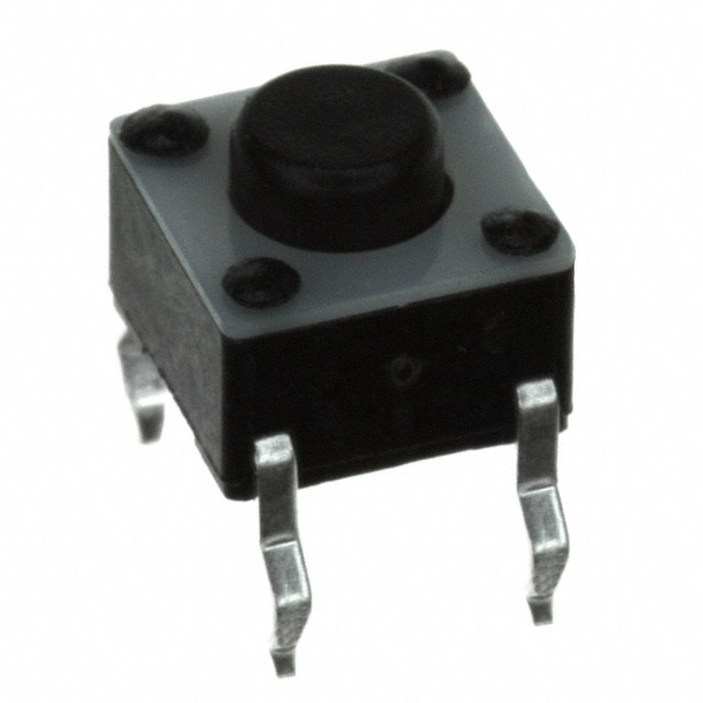
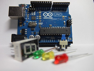
For this series, you will need the following components:
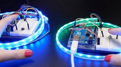
Connect the hardware as follows on your breadboard:

We will be using the LED and button for this tutorial. You will not need to use the TMP102 breakout board.
Start by copying the blinky project to use as a template. Navigate to your workspace directory and copy the entire usb-serial project:
cd workspace/apps
cp -r blinky timer-interrupt
cd timer-interrupt
If a target/ directory exists from previous builds, you can delete it to start fresh (though Cargo will handle rebuilding automatically):
rm -rf target
We need to make several changes to Cargo.toml to support interrupt handling.
[package]
name = "timer-interrupt"
version = "0.1.0"
edition = "2024"

[dependencies]
rp235x-hal = { version = "0.3.0", features = ["rt", "critical-section-impl"] }
embedded-hal = "1.0.0"
cortex-m = "0.7.7"
cortex-m-rt = "0.7.5"
fugit = "0.3.7"
critical-section = "1.2.0"
First, update the package name from "blinky" to "timer-interrupt". Next, we'll add two new dependencies that are essential for working with interrupts safely. Add fugit = "0.3.7", which provides convenient types for working with time durations and helps us specify alarm schedules in human-readable units like milliseconds.
You’ll also need to add critical-section = "1.2.0", which provides the critical section mechanism we'll use to safely access shared data between the main program and interrupt handlers. Critical sections ensure that when an interrupt handler and main code both need to access the same global variable, they can do so without race conditions by temporarily disabling interrupts during access.
You’ll need to rewrite most of src/main.rs:
#![no_std]
#![no_main]

// We need to write our own panic handler
use core::panic::PanicInfo;

// Let us modify data with only immutable reference (enforce borrow rules at runtime)
use core::cell::RefCell;

// Embedded mutex (no threads): access to data by one piece of code at a time
use critical_section::Mutex;

// Alias our HAL
use rp235x_hal as hal;

// Import traits for embedded abstractions
use embedded_hal::digital::StatefulOutputPin;

// Imports for the pin definition
use hal::gpio::{FunctionSio, Pin, PullDown, SioOutput};

// Imports for the timer interrupt
use hal::pac::interrupt;
use hal::timer::{Alarm, Alarm0, CopyableTimer0};

// Direct access to the nested vectored interrupt controller (NVIC)
use cortex_m::peripheral::NVIC;

// Help with timing and duration
use fugit::MicrosDurationU32;

// Custom panic handler: just loop forever
#[panic_handler]
fn panic(_info: &PanicInfo) -> ! {
    loop {}
}

// Copy boot metadata to .start_block so Boot ROM knows how to boot our program
#[unsafe(link_section = ".start_block")]
#[used]
pub static IMAGE_DEF: hal::block::ImageDef = hal::block::ImageDef::secure_exe();

// Set external crystal frequency
const XOSC_CRYSTAL_FREQ: u32 = 12_000_000;

// Global state for the alarm, LED, and timer (similar to the working example)
type LedPin = Pin<hal::gpio::bank0::Gpio15, FunctionSio<SioOutput>, PullDown>;

// Global state for the alarm and LED (wrapped in Mutex for interrupt safety)
static G_ALARM: Mutex<RefCell<Option<Alarm0<CopyableTimer0>>>> = Mutex::new(RefCell::new(None));
static G_LED: Mutex<RefCell<Option<LedPin>>> = Mutex::new(RefCell::new(None));

// Main entrypoint (custom defined for embedded targets)
#[hal::entry]
fn main() -> ! {
    // Get ownership of hardware peripherals
    let mut pac = hal::pac::Peripherals::take().unwrap();

    // Set up the watchdog and clocks
    let mut watchdog = hal::Watchdog::new(pac.WATCHDOG);
    let clocks = hal::clocks::init_clocks_and_plls(
        XOSC_CRYSTAL_FREQ,
        pac.XOSC,
        pac.CLOCKS,
        pac.PLL_SYS,
        pac.PLL_USB,
        &mut pac.RESETS,
        &mut watchdog,
    )
    .ok()
    .unwrap();

    // Single-cycle I/O block (fast GPIO)
    let sio = hal::Sio::new(pac.SIO);

    // Split off ownership of Peripherals struct, set pins to default state
    let pins = hal::gpio::Pins::new(
        pac.IO_BANK0,
        pac.PADS_BANK0,
        sio.gpio_bank0,
        &mut pac.RESETS,
    );

    // Configure pin, get ownership of that pin
    let led_pin = pins.gpio15.into_push_pull_output();

    // Move ownership of TIMER0 peripheral to create Timer struct
    let mut timer = hal::Timer::new_timer0(pac.TIMER0, &mut pac.RESETS, &clocks);

    // Create an alarm from the timer
    let mut alarm = timer.alarm_0().unwrap();

    // Set the alarm to trigger in 500 ms
    let _ = alarm.schedule(MicrosDurationU32::millis(500));

    // Enable alarm interrupt
    alarm.enable_interrupt();

    // Move alarm and LED to global state for interrupt handler
    critical_section::with(|cs| {
        G_ALARM.borrow(cs).replace(Some(alarm));
        G_LED.borrow(cs).replace(Some(led_pin));
    });

    // Enable the interrupt line
    unsafe {
        NVIC::unmask(hal::pac::Interrupt::TIMER0_IRQ_0);
    }

    // Main loop - do nothing
    loop {
        cortex_m::asm::wfi();
    }
}

// Interrupt service routine (ISR)
#[interrupt]
fn TIMER0_IRQ_0() {
    critical_section::with(|cs| {
        // Borrow the alarm and LED from global state
        let mut alarm_ref = G_ALARM.borrow(cs).borrow_mut();
        let mut led_ref = G_LED.borrow(cs).borrow_mut();

        // Get mutable references
        if let (Some(alarm), Some(led)) = (alarm_ref.as_mut(), led_ref.as_mut()) {
            // Clear the interrupt
            alarm.clear_interrupt();

            // Toggle the LED
            let _ = led.toggle();

            // Schedule next interrupt in 500ms
            let _ = alarm.schedule(fugit::MicrosDurationU32::millis(500));
        }
    });
}
We introduce several new concepts related to interrupt handling and safe concurrent access to shared data. At the top of the file, we import core::cell::RefCell and critical_section::Mutex. These types work together to provide safe access to data shared between the main program and interrupt handlers. RefCell enables interior mutability, allowing us to modify data through an immutable reference by enforcing Rust's borrowing rules at runtime rather than compile time.
The Mutex from critical_section wraps the RefCell to ensure only one piece of code (either main or the ISR) can access the shared data at a time by temporarily disabling interrupts during access. We also import types specific to our needs: StatefulOutputPin trait for toggling the LED, specific pin and timer types from the HAL, interrupt and NVIC for managing interrupts, and MicrosDurationU32 from fugit for specifying time durations.
The most significant change is the introduction of global static variables wrapped in thread-safety primitives. We define G_ALARM and G_LED as global statics of type Mutex<refcell<option<...>>>, creating a pattern common in embedded Rust for sharing resources between main code and ISRs. The Option type allows these to start as None and be populated later with actual alarm and LED instances. We also create a type alias LedPin to avoid repeating the complex generic pin type throughout our code.
In the main function, after initializing the hardware and creating the LED pin and timer alarm, we configure the alarm to trigger after 500 milliseconds using alarm.schedule(MicrosDurationU32::millis(500)) and enable its interrupt with alarm.enable_interrupt(). We then move ownership of both the alarm and LED into the global variables using critical_section::with(), which executes a closure with interrupts disabled to safely transfer ownership.
The final setup step unmasks the timer interrupt in the NVIC using unsafe { NVIC::unmask(hal::pac::Interrupt::TIMER0_IRQ_0) }. We use an unsafe{...} block here to let the compiler know we intend to manipulate a register. Without the unsafe keyword, the build process would fail. Note that directly manipulating interrupt controllers can cause undefined behavior if done incorrectly, so we must be very careful.
Once interrupts are enabled, the main loop enters an infinite loop that simply calls cortex_m::asm::wfi() (wait for interrupt), putting the processor into a low-power sleep state until an interrupt wakes it. The actual work happens in the interrupt service routine, marked with #[interrupt] and named TIMER0_IRQ_0 to match the specific interrupt source.
Inside the ISR, we use critical_section::with() to safely borrow mutable references to the alarm and LED from the global state. We clear the interrupt flag with alarm.clear_interrupt() to acknowledge we've handled it, toggle the LED state with led.toggle(), and reschedule the alarm for another 500 milliseconds. This pattern of hardware triggering an interrupt, ISR handling it quickly, and rescheduling the next event creates an efficient, event-driven system where the processor sleeps between interrupts rather than constantly polling.
Save all your work. In the terminal, build the program from the project directory:
cargo build
Next, convert your compiled binary file into a .uf2 file that can be uploaded to the RP2350’s bootloader. We can find our binary in the corresponding folder. In a terminal, enter:
picotool uf2 convert target/thumbv8m.main-none-eabihf/debug/i2c-tmp102 -t elf firmware.uf2 -t uf2
Press and hold the BOOTSEL button on the Pico 2, plug in the USB cable to the Pico 2, and then release the BOOTSEL button. That should put your RP2350 into bootloader mode, and it should enumerate as a mass storage device on the computer.
On your host computer, navigate to workspace/apps/i2c-tmp102/, copy firmware.uf2, and paste it into the root of the RP2350 drive (should be named “RP2350” on your computer).
Once it copies, the board should automatically reboot. You should see the LED flashing every second!

Not the most impressive demo, as it performs the exact same action as in the second tutorial. However, you know that it’s flashing due to interrupts instead of a wait cycle, which is ultimately saving power.
Your challenge is to create a button-controlled LED toggle using GPIO pin change interrupts instead of polling in the main loop. I recommend implementing some simple debouncing logic: set a global flag in the ISR when the button is pressed, then in the main loop, check that flag, clear it, wait 50 milliseconds, and only toggle the LED if the button is still pressed. timer.delay_ms(50) is acceptable in the main loop (so you don’t need to set up a separate timer interrupt to fire after 50 ms).
You can see my solution here.
At this point, you should have a decent working knowledge of Rust along with some of the important building blocks for writing embedded programs. We will not require any additional reading in the Rust Book for the rest of the series. In the next episode, we’ll see how to connect the Raspberry Pi Debug Probe to perform step-through debugging.
Find the full Intro to Embedded Rust series here.