I’m Reviving the Openwheel Project!
2026-03-06 | By Zach Hipps
I’m not even sure I can find this thing after I moved. I might have to travel to the deep, dark corners of my workshop because this is something I built quite some time ago. It’s not back there... maybe it’s, oh, yeah. I think it’s down here. Hold on a second. Here is what I want to show you. It’s covered in sawdust, but this is the Open Wheel. Back in 2021, I built an open-source, self-balancing skateboard inspired by the Onewheel. This project wasn't just a one-off stunt for a couple of YouTube videos; I really wanted to document the whole process and make it open source so that you could build it just like I did. That’s why I uploaded all the design files to a GitHub repository and created a digital build guide. It was an enormous project to tackle, so it was really exciting to see pictures and emails from people who actually built these on their own.


Over the past five years or so, this project has stayed in the back of my mind because there are some things I didn't get quite right the first time. For starters, I built this thing way too big. I based the whole design around a huge LiPo battery pack; it had no business being in a self-balancing board. As a result, the whole board ended up way too heavy. I also wasn't a fan of the 3D-printed parts, and the electronics were, frankly, a little janky. I think it’s time to revive this project. I want to revamp the whole thing from the ground up and fix everything I missed.


The vision for this project has evolved. There is a huge community built around the Onewheel platform, and it’s clear that people want two things: the right to repair and the ability to upgrade. Unfortunately, Future Motion (the company behind Onewheel) makes this very difficult. Their firmware is locked down to limit liability, and their parts are proprietary. If your board breaks, you have to box it up, ship it off, and wait weeks. For most people, that's fine. But for tinkers and engineers like us, we want to fix it ourselves. It’s time this category gets a community-owned, open-source alternative. This isn't going to be a quick afternoon project. It’s more like a long-term quest. I feel like Frodo bringing the Ring of Power to Mount Doom, it’s going to take a while to get it right.

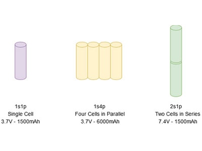
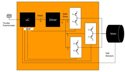
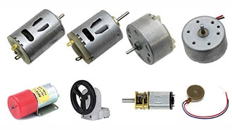
The biggest hurdle people email me about is the 10-inch hub motor. These brushless DC motors are getting harder to find. I did some digging and found a model called the phub-188pw on the vendor’s website. Interestingly, while the original was rated for 800W, I found a version of the same motor claiming a massive 4000W output at up to 72V. I’m pretty skeptical of these claims, so I decided to order one to see if it’s real or if I'm just getting scammed. After a few weeks, the new motor finally arrived. For my first order of business, I wanted to try cracking it open. Removing the rubber tire took several hours and was way harder than expected, but I eventually got to the guts of it. Inside, you have the rotor (the outside part with permanent magnets) and the stator (the inside part with enameled copper wire). By counting the components, I found 27 coil windings on the stator and 30 permanent magnets on the rotor. This is a crucial detail because the number of windings must be a multiple of three for a three-phase motor. Since 27 divided by 3 equals 9, there are 9 sets of windings per phase. I used an online calculator to determine the winding scheme. For a low-speed, high-torque hub motor like this, it is almost certainly wired in a Wye configuration. To get this motor moving efficiently and quietly, we use a Field Oriented Control (FOC) controller. FOC sends out a sinusoidal waveform and relies on positional feedback to know exactly where the rotor is. I found the Hall-effect sensors embedded in the stator's laminated layers, which provide feedback to the controller.


For the "brain" of the board, I upgraded to a Flipsky VESC 75-100. This controller can handle up to 75V and 100A continuous current. Unlike the janky version one, this has a built-in anti-spark switch and a Bluetooth module for real-time stats.


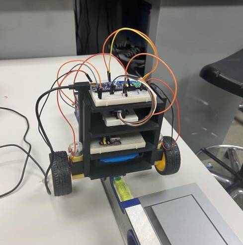
I built a temporary testing frame out of aluminum extrusion and 3D-printed brackets to keep the motor from rolling off my workbench. After connecting it to my benchtop power supply at 36V and running the VESC detection software, it spun up perfectly. It’s incredibly smooth and quiet. Using the VESC mobile app, I can view real-time data such as current, duty cycle, and temperature. The real question remains: is this actually a 4000W motor? I have a hard time believing it, especially since I have other, beefier motors with the same rating. To prove it, I need to build a dynamometer (or dyno) to measure the mechanical output power. We can easily calculate the electrical input power, Pin, but the mechanical output, Pout, is what matters. To find the efficiency, we use the formula:
Efficiency = Pout / Pin

To get Pout, I need to measure the RPM and the torque. Measuring RPM is easy, but torque requires a load cell to convert the rotational force into an electrical signal. This will be my next big step in the background.


This is just the beginning of the Open Wheel revival. I’m looking for collaborators and project supporters to help turn this into a truly community-owned platform. If you’re a coder, an engineer, or just someone who wants to see open-source hardware win, I’d love to have you on board.