メーカー品番 SC1631
RASPBERRY PI PICO 2 RP2350
Raspberry Pi
Microcontrollers Raspberry Pi MCU
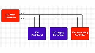
In this tutorial, we'll explore how to communicate with external digital devices using Inter-Integrated Circuit (I2C), one of the most popular communication protocols in embedded systems. I2C is a two-wire serial protocol that allows a microcontroller to talk to multiple peripherals, such as sensors, displays, memory chips, and more. We'll build on our USB serial template from the previous tutorial to create a program that reads temperature data from a TMP102 sensor and displays it over USB serial when you press a button.
Note that all code for this series can be found in this GitHub repository.
We’ll cover how to configure I2C pins on the RP2350, initialize the I2C peripheral with the proper clock speed, and perform read and write operations to communicate with I2C devices. You'll learn how to handle I2C addressing, register access patterns common to many sensors, and convert raw sensor data into meaningful values. We'll also explore practical error handling using Rust's Result type, working with fixed-size strings without heap allocation using the heapless crate, and implementing button-triggered readings using GPIO input pins. This combination of I2C communication and USB serial output creates a versatile template for interfacing with countless I2C sensors and devices in your future embedded Rust projects.
For this series, you will need the following components:
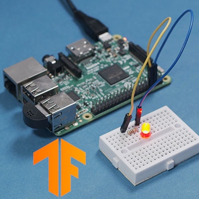
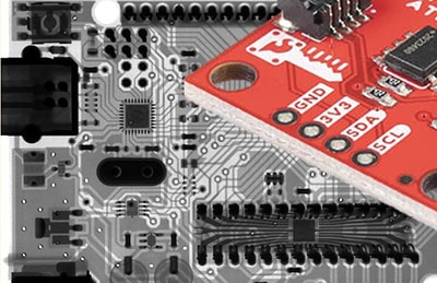
Connect the hardware as follows on your breadboard:

We will be using the TMP102 temperature sensor and button in this tutorial. We will not need the LED.
We'll start by copying our USB serial project as a foundation, since we'll be using USB serial communication to display sensor readings. Navigate to your workspace directory and copy the entire usb-serial project:
cd workspace/apps
cp -r usb-serial i2c-tmp102
cd i2c-tmp102
If a target/ directory exists from previous builds, you can delete it to start fresh (though Cargo will handle rebuilding automatically):
rm -rf target
Next, update the package name in Cargo.toml from "usb-serial" to "i2c-tmp102". We'll also need to add one new dependency: the heapless crate, which provides fixed-size data structures that work without heap allocation. Add this line to your [dependencies] section:
[package]
name = "i2c-tmp102"
version = "0.1.0"
edition = "2024"

[dependencies]
rp235x-hal = { version = "0.3.0", features = ["rt", "critical-section-impl"] }
embedded-hal = "1.0.0"
cortex-m = "0.7.7"
cortex-m-rt = "0.7.5"
usb-device = "0.3.2"
usbd-serial = "0.2.2"
heapless = "0.8.0"

[profile.dev]

[profile.release]
opt-level = "s"
lto = true
codegen-units = 1
strip = true
The heapless crate is particularly useful in embedded systems for working with strings and collections without requiring the heap. In our case, we'll use heapless::String to format temperature readings for printing over USB serial. All other configuration files (.cargo/config.toml and memory.x) remain unchanged, as we are building on top of the serial demo application we made in a previous tutorial.
In src/main.rs, you will need to make a few changes from the original usb-serial application. Here is the entire main.rs:
#![no_std]
#![no_main]

// We need to write our own panic handler
use core::panic::PanicInfo;

// Alias our HAL
use rp235x_hal as hal;

// Bring GPIO structs/functions into scope
use hal::gpio::{FunctionI2C, Pin};

// USB device and Communications Class Device (CDC) support
use usb_device::{class_prelude::*, prelude::*};
use usbd_serial::SerialPort;

// I2C structs/functions
use embedded_hal::{digital::InputPin, i2c::I2c};

// Used for the rate/frequency type
use hal::fugit::RateExtU32;

// For working with non-heap strings
use core::fmt::Write;
use heapless::String;

// Custom panic handler: just loop forever
#[panic_handler]
fn panic(_info: &PanicInfo) -> ! {
    loop {}
}

// Copy boot metadata to .start_block so Boot ROM knows how to boot our program
#[unsafe(link_section = ".start_block")]
#[used]
pub static IMAGE_DEF: hal::block::ImageDef = hal::block::ImageDef::secure_exe();

// Constants
const XOSC_CRYSTAL_FREQ: u32 = 12_000_000; // External crystal on board
const TMP102_ADDR: u8 = 0x48; // Device address on bus
const TMP102_REG_TEMP: u8 = 0x0; // Address of temperature register

// Main entrypoint (custom defined for embedded targets)
#[hal::entry]
fn main() -> ! {
    // Get ownership of hardware peripherals
    let mut pac = hal::pac::Peripherals::take().unwrap();

    // Set up the watchdog and clocks
    let mut watchdog = hal::Watchdog::new(pac.WATCHDOG);
    let clocks = hal::clocks::init_clocks_and_plls(
        XOSC_CRYSTAL_FREQ,
        pac.XOSC,
        pac.CLOCKS,
        pac.PLL_SYS,
        pac.PLL_USB,
        &mut pac.RESETS,
        &mut watchdog,
    )
    .ok()
    .unwrap();

    // Single-cycle I/O block (fast GPIO)
    let sio = hal::Sio::new(pac.SIO);

    // Split off ownership of Peripherals struct, set pins to default state
    let pins = hal::gpio::Pins::new(
        pac.IO_BANK0,
        pac.PADS_BANK0,
        sio.gpio_bank0,
        &mut pac.RESETS,
    );

    // Configure button pin
    let mut btn_pin = pins.gpio14.into_pull_up_input();

    // Configure I2C pins
    let sda_pin: Pin<_, FunctionI2C, _> = pins.gpio18.reconfigure();
    let scl_pin: Pin<_, FunctionI2C, _> = pins.gpio19.reconfigure();

    // Initialize and take ownership of the I2C peripheral
    let mut i2c = hal::I2C::i2c1(
        pac.I2C1,
        sda_pin,
        scl_pin,
        100.kHz(),
        &mut pac.RESETS,
        &clocks.system_clock,
    );

    // Initialize the USB driver
    let usb_bus = UsbBusAllocator::new(hal::usb::UsbBus::new(
        pac.USB,
        pac.USB_DPRAM,
        clocks.usb_clock,
        true,
        &mut pac.RESETS,
    ));

    // Configure the USB as CDC
    let mut serial = SerialPort::new(&usb_bus);

    // Create a USB device with a fake VID/PID
    let mut usb_dev = UsbDeviceBuilder::new(&usb_bus, UsbVidPid(0x16c0, 0x27dd))
        .strings(&[StringDescriptors::default()
            .manufacturer("Fake company")
            .product("Serial port")
            .serial_number("TEST")])
        .unwrap()
        .device_class(2) // from: https://www.usb.org/defined-class-codes
        .build();

    // Read buffer
    let mut rx_buf = [0u8; 2];
    let mut output = String::<64>::new();

    // Superloop
    let mut prev_pressed = false;
    loop {
        // Needs to be called at least every 10 ms
        let _ = usb_dev.poll(&mut [&mut serial]);

        // Get button state
        // let btn_pressed: bool = match btn_pin.is_low() {
        //     Ok(state) => state,
        //     Err(_e) => false,
        // };
        let btn_pressed = btn_pin.is_low().unwrap_or(false);

        if btn_pressed && (!prev_pressed) {
            // Read from sensor
            let result = i2c.write_read(TMP102_ADDR, &[TMP102_REG_TEMP], &mut rx_buf);
            if result.is_err() {
                let _ = serial.write(b"ERROR: Could not read temperature\r\n");
                continue;
            }

            // Convert raw reading (signed 12-bit value) into Celsius
            let temp_raw = ((rx_buf[0] as u16) << 8) | (rx_buf[1] as u16);
            let temp_signed = (temp_raw as i16) >> 4;
            let temp_c = (temp_signed as f32) * 0.0625;

            // Print out value
            output.clear();
            write!(&mut output, "Temperature: {:.2} deg C\r\n", temp_c).unwrap();
            let _ = serial.write(output.as_bytes());
        }

        // Save button pressed state for next iteration
        prev_pressed = btn_pressed;
    }
}
The main changes to our program involve adding I2C functionality and button input to trigger sensor readings. At the top of the file, we import several new items: hal::gpio::FunctionI2C and Pin for configuring I2C pins, embedded_hal::digital::InputPin for reading button state, embedded_hal::i2c::I2c trait for I2C operations, and hal::fugit::RateExtU32, which provides a convenient extension method for specifying clock frequencies (like 100.kHz()). We also import core::fmt::Write and heapless::String to format temperature values into strings without using heap allocation. Three constants define our I2C configuration: TMP102_ADDR (0x48) is the device address of the sensor on the I2C bus, and TMP102_REG_TEMP (0x0) specifies the register address we'll read to get temperature data. These values come from the TMP102 datasheet and are specific to how this particular sensor works.
The hardware initialization adds GPIO and I2C setup to our existing USB serial code. We configure GPIO14 as a pull-up input for the button using into_pull_up_input(), which means the pin reads high (logic 1) by default and goes low when the button connects it to ground. For I2C, we need to reconfigure GPIO18 and GPIO19 to serve their alternate I2C function rather than their regular GPIO function. The .reconfigure() method changes these pins to FunctionI2C, and we explicitly annotate the types as Pin<_, FunctionI2C, > to make the function selection clear. We then initialize the I2C peripheral by calling hal::I2C::i2c1(), passing the I2C1 peripheral, the configured pins, a clock speed of 100 kHz (standard I2C speed), and references to the reset controller and system clock. This gives us an i2c object that implements the I2c trait from embedded-hal, providing methods like writeread() for communicating with I2C devices.
The main loop implements a simple button-triggered sensor reading pattern. We poll the USB device as before, then check if the button is pressed using btn_pin.is_low().unwrap_or(false), which returns true if the pin reads low (button pressed) or false if there's an error reading the pin. To avoid multiple readings from a single button press, we track the previous button state and only take a reading when the button transitions from unpressed to pressed. When triggered, we use i2c.write_read() to perform a combined write-then-read operation: first writing the register address (TMP102_REG_TEMP) to tell the sensor which register we want to read, then reading 2 bytes of temperature data into our buffer. If the I2C operation succeeds, we convert the raw 12-bit signed temperature value into degrees Celsius using bit shifting and scaling (the TMP102 uses 0.0625°C per bit). We format the result into a heapless::String using the write! macro (similar to format! but for fixed-size strings) and send it over USB serial.
Save all your work. In the terminal, build the program from the project directory:
cargo build
Next, convert your compiled binary file into a .uf2 file that can be uploaded to the RP2350’s bootloader. We can find our binary in the corresponding folder. In a terminal, enter:
picotool uf2 convert target/thumbv8m.main-none-eabihf/debug/i2c-tmp102 -t elf firmware.uf2 -t uf2
Press and hold the BOOTSEL button on the Pico 2, plug in the USB cable to the Pico 2, and then release the BOOTSEL button. That should put your RP2350 into bootloader mode, and it should enumerate as a mass storage device on the computer.
On your host computer, navigate to workspace/apps/i2c-tmp102/, copy firmware.uf2, and paste it into the root of the RP2350 drive (should be named “RP2350” on your computer).
Once it copies, the board should automatically reboot. Use a serial terminal program (e.g. PuTTY, minicom) to connect to your Pico 2. Press the button on your board, and you should see the temperature logged to the screen! Feel free to touch or lightly breathe on the sensor to watch the values rise.

You might notice that the temperature is sometimes logged to the serial terminal multiple times for each button press. This is due to a phenomenon known as “contact bounce,” where the electrical contacts of the button rapidly connect and disconnect within the span of a few microseconds, causing the program to register multiple presses.
Your challenge, should you choose to accept it, is to add a software-based debounce system to the code so that only one temperature is logged to the terminal for each button press. Anne Barela over at Adafruit has a great write-up for software debouncing. Your job is to take this Arduino code and translate it to Rust for our I2C TMP102 demo.
My solution for this exercise can be found here.
Next time, we will cover generics and traits in Rust. As a result, I recommend reading sections 10.1 and 10.2 in the Rust Book as well as tackling the options, generics, and traits exercises in rustlings.
Find the full Intro to Embedded Rust series here.