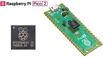
メーカー品番 SC1631
RASPBERRY PI PICO 2 RP2350
Raspberry Pi
In this tutorial, we create our first embedded Rust application: a blinking LED program for the Raspberry Pi Pico 2. While this might seem like a simple project, it introduces several fundamental concepts in embedded systems programming, including direct hardware access, memory-mapped peripherals, and bare-metal development without an operating system.
Note that all code for this series can be found in this GitHub repository.
We will avoid using a framework like Embassy for now so you can see how all the gritty details work. Note that we will still use a hardware abstraction layer (HAL) to help us set up clocks and toggle GPIO pins. Specifically, we will rely on the community-provided rp-hal, which has been created to support Raspberry Pi RPxxxx microcontrollers, such as the RP2040 and RP2350.
If you have not done so already, I recommend reading chapters 1-3 in the Rust Book and doing the rustlings exercises on variables, functions, and if statements. These sections cover some of the basic concepts and program flow in Rust. We will build on top of that to work with our Raspberry Pi Pico 2.
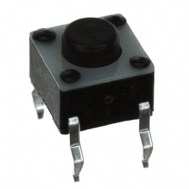
For this series, you will need the following components:
Connect the hardware as follows on your breadboard:

You are welcome to install Rust locally on your computer, but I recommend using the Docker image built for this series, as it pins the various Rust and library versions, along with ensuring a unified experience across the various operating systems. To use Docker, you will need to install Docker Desktop on your computer.
If you have not done so already, download the series’ associated GitHub repository: https://github.com/ShawnHymel/introduction-to-embedded-rust (e.g., using git clone or clicking Code > Download ZIP). From your computer, navigate into the repo’s directory and build the Docker image:
cd introduction-to-embedded-rust
docker build -t env-embedded-rust .
You can either use VS Code with the Dev Containers extension, or you can run the image directly in a terminal. Note that in the videos, I use VS Code with Dev Containers. If you wish to run the image directly, run the following command in a terminal:
docker run --rm -it -p 3000:3000 -v "$(pwd)/workspace:/home/student/workspace" -w /workspace env-embedded-rust
With the image running, you can write code using any editor you like, just make sure to save it in the workspace/ directory, as it is mapped to the container. You can then use the interactive terminal in the container to build your Rust projects.
Note: feel free to delete or move the projects already in apps/ and libraries/. We will be creating new ones from scratch.
In the Docker container, navigate to workspace/apps/ and run the cargo init command to initialize the project space. Note that you can create the files manually, but Cargo makes the process a little faster.
cd /home/student/workspace/apps
cargo init blinky --bin --vcs none
The cargo init command creates the necessary boilerplate files and folders to get started with a basic Rust project, including a “hello, world” example in src/main.rs. We add “blinky” to the command to give the project a name. The --bin flag explicitly specifies that you want to create a binary (executable) project rather than a library, and --vcs none tells Cargo not to initialize a Git repository (as we are already inside a Git repository anyway).
In addition to these boilerplate files, you will need to add .cargo/config.toml and memory.x to create a final project directory structure as follows:
workspace/apps/
 └── blinky/
 ├── .cargo/
 │ └── config.toml
 ├── src/
 │ └── main.rs
 ├── Cargo.toml
 └── memory.x
Fill out the following code in each of the files. We will go through each one and explain what is happening.
[package]
name = "blinky"
version = "0.1.0"
edition = "2024"
[dependencies]
rp235x-hal = { version = "0.3.0", features = ["rt", "critical-section-impl"] }
embedded-hal = "1.0.0"
cortex-m = "0.7.7"
cortex-m-rt = "0.7.5"
The Cargo.toml file is written in TOML (Tom's Obvious, Minimal Language), a configuration file format that uses key-value pairs organized into tables (similar to JSON or YAML). This file defines your project's metadata and dependencies. Under the [package] table, you'll see basic information like the project name, version, and edition. The edition field specifies which snapshot of Rust language rules and syntax your project uses (e.g., "2024"). Rust maintains backward compatibility across editions, so you can mix dependencies that use different editions without issues.
The [dependencies] table is where we specify the crates (Rust's term for packages or libraries) our embedded project needs. We're using rp235x-hal, a community-provided Hardware Abstraction Layer (HAL) for the RP2350 chip that provides a safe, high-level interface to the hardware peripherals. The features we enable ("rt" for runtime support and "critical-section-impl" for interrupt-safe code) are crucial for embedded development. We also include embedded-hal, which provides common traits and interfaces maintained by Rust's official embedded working group, allowing us to write platform-agnostic code. The cortex-m and cortex-m-rt crates give us access to ARM Cortex-M CPU peripherals and handle the startup code, interrupt vectors, and memory initialization that an operating system would normally manage.
[build]
# Target is the Cortex-M33 with FPU enabled
target = "thumbv8m.main-none-eabihf"

[target.thumbv8m.main-none-eabihf]
rustflags = [
  # Compiler optimizations
  "-C", "target-cpu=cortex-m33",    # Target the Cortex-M33

  # Linker directives
  "-C", "link-arg=-Tlink.x",  # Use link.x script with cortex-m-rt to lay out memory
  "-C", "link-arg=--nmagic",  # Prevent padding memory between sections to save space
]
The .cargo/config.toml file tells Cargo how to build your project for embedded targets. Most desktop Rust projects don't need this file because Cargo defaults to building for your host system, but embedded development requires cross-compilation to a different architecture. The [build] section specifies our target as thumbv8m.main-none-eabihf, which represents the Thumb-2 instruction set for ARMv8-M architecture with hardware floating-point support (which is what the Cortex-M33 processor in the RP2350 uses). The naming convention breaks down as: thumbv8m (ARMv8-M architecture), main (main profile with full instruction set), none (no operating system), eabihf (embedded application binary interface with hardware float).
The [target.thumbv8m.main-none-eabihf] section contains rustflags that pass additional instructions to the Rust compiler and linker. The -C target-cpu=cortex-m33 flag optimizes code specifically for the Cortex-M33 processor. The linker directives are equally important, -C link-arg=-Tlink.x tells the linker to use the link.x script provided by the cortex-m-rt crate, which works together with our memory.x file to properly lay out the program in memory. The --nmagic flag prevents the linker from adding padding between memory sections, saving precious flash space on our microcontroller. Without this configuration file, Cargo would attempt to build a standard desktop application that couldn't run on our Pico 2.
MEMORY {
    /*
     * The RP2350 has either external or internal flash.
     *
     * 2 MiB is a safe default here, although a Pico 2 has 4 MiB.
     */
    FLASH : ORIGIN = 0x10000000, LENGTH = 2048K
    /*
     * RAM consists of 8 banks, SRAM0-SRAM7, with a striped mapping.
     * This is usually good for performance, as it distributes load on
     * those banks evenly.
     */
    RAM : ORIGIN = 0x20000000, LENGTH = 512K
    /*
     * RAM banks 8 and 9 use a direct mapping. They can be used to have
     * memory areas dedicated for some specific job, improving predictability
     * of access times.
     * Example: Separate stacks for core0 and core1.
     */
    SRAM8 : ORIGIN = 0x20080000, LENGTH = 4K
    SRAM9 : ORIGIN = 0x20081000, LENGTH = 4K
}

SECTIONS {
    /* ### Boot ROM info
     *
     * Goes after .vector_table, to keep it in the first 4K of flash
     * where the Boot ROM (and picotool) can find it
     */
    .start_block : ALIGN(4)
    {
        __start_block_addr = .;
        KEEP(*(.start_block));
        KEEP(*(.boot_info));
    } > FLASH

} INSERT AFTER .vector_table;

/* move .text to start /after/ the boot info */
_stext = ADDR(.start_block) + SIZEOF(.start_block);

SECTIONS {
    /* ### Picotool 'Binary Info' Entries
     *
     * Picotool looks through this block (as we have pointers to it in our
     * header) to find interesting information.
     */
    .bi_entries : ALIGN(4)
    {
        /* We put this in the header */
        __bi_entries_start = .;
        /* Here are the entries */
        KEEP(*(.bi_entries));
        /* Keep this block a nice round size */
        . = ALIGN(4);
        /* We put this in the header */
        __bi_entries_end = .;
    } > FLASH
} INSERT AFTER .text;

SECTIONS {
    /* ### Boot ROM extra info
     *
     * Goes after everything in our program, so it can contain a signature.
     */
    .end_block : ALIGN(4)
    {
        __end_block_addr = .;
        KEEP(*(.end_block));
        __flash_binary_end = .;
    } > FLASH

} INSERT AFTER .uninit;

PROVIDE(start_to_end = __end_block_addr - __start_block_addr);
PROVIDE(end_to_start = __start_block_addr - __end_block_addr);
The memory.x file is a linker script that defines the memory map for the RP2350 chip, telling the linker where to place different parts of your program in flash and RAM. The MEMORY block specifies the physical memory regions available on the chip: FLASH starts at address 0x10000000 with 2 MiB of space. Note that the Pico 2 actually has 4 MiB (feel free to adjust this if needed), and RAM starts at 0x20000000 with 512 KiB. The RP2350's RAM consists of eight banks (SRAM0-SRAM7) that use striped mapping to distribute memory access evenly across banks for better performance. Two additional banks (SRAM8 and SRAM9) use direct mapping and can be dedicated to specific tasks like separate stacks for each processor core, though we won't use them in this simple example.
The SECTIONS blocks define special memory regions required by the RP2350's boot process and tooling. The .start_block section contains boot metadata that the Boot ROM (a small, permanent program burned into the chip) reads to know how to start your program. This must be placed in the first 4K of flash where the Boot ROM expects to find it. The .bi_entries section holds "Binary Info" entries that tools like picotool use to extract metadata about your program. Finally, the .end_block section goes at the end of your program and can contain signatures for secure boot validation (though we're not using that feature in this tutorial). These special sections work together with the cortex-m-rt startup code to ensure your program boots correctly on the RP2350, handling details that frameworks like Arduino or the Pico SDK normally manage for you automatically.
When you specify -C link-arg=-Tlink.x in your .cargo/config.toml, you're telling the linker to use the link.x script provided by cortex-m-rt. That link.x script, in turn, includes and processes the memory.x file that you provide in your project root. The cortex-m-rt crate uses the memory regions you define in memory.x to properly set up the vector table, initialize the stack, and lay out all the program sections in flash and RAM according to your specific microcontroller's memory map.
Note that for simplicity, we are copying the memory.x file directly from the rp-hal/rp235x-hal-examples/ directory, as was already configured to work for the Raspberry Pi Pico 2 (and other similar RP2350-based boards).
#![no_std]
#![no_main]

// We need to write our own panic handler
use core::panic::PanicInfo;

// Alias our HAL
use rp235x_hal as hal;

// Import traits for embedded abstractions
use embedded_hal::delay::DelayNs;
use embedded_hal::digital::OutputPin;

// Custom panic handler: just loop forever
#[panic_handler]
fn panic(_info: &PanicInfo) -> ! {
    loop {}
}

// Copy boot metadata to .start_block so Boot ROM knows how to boot our program
#[unsafe(link_section = ".start_block")]
#[used]
pub static IMAGE_DEF: hal::block::ImageDef = hal::block::ImageDef::secure_exe();

// Set external crystal frequency
const XOSC_CRYSTAL_FREQ: u32 = 12_000_000;

// Main entrypoint (custom defined for embedded targets)
#[hal::entry]
fn main() -> ! {
    // Get ownership of hardware peripherals
    let mut pac = hal::pac::Peripherals::take().unwrap();

    // Set up the watchdog and clocks
    let mut watchdog = hal::Watchdog::new(pac.WATCHDOG);
    let clocks = hal::clocks::init_clocks_and_plls(
        XOSC_CRYSTAL_FREQ,
        pac.XOSC,
        pac.CLOCKS,
        pac.PLL_SYS,
        pac.PLL_USB,
        &mut pac.RESETS,
        &mut watchdog,
    )
    .ok()
    .unwrap();

    // Single-cycle I/O block (fast GPIO)
    let sio = hal::Sio::new(pac.SIO);

    // Split off ownership of Peripherals struct, set pins to default state
    let pins = hal::gpio::Pins::new(
        pac.IO_BANK0,
        pac.PADS_BANK0,
        sio.gpio_bank0,
        &mut pac.RESETS,
    );

    // Configure pin, get ownership of that pin
    let mut led_pin = pins.gpio15.into_push_pull_output();

    // Move ownership of TIMER0 peripheral to create Timer struct
    let mut timer = hal::Timer::new_timer0(pac.TIMER0, &mut pac.RESETS, &clocks);

    // Blink loop
    loop {
        led_pin.set_high().unwrap();
        timer.delay_ms(500);
        led_pin.set_low().unwrap();
        timer.delay_ms(500);
    }
}
The first thing you'll notice in main.rs is the #![no_std] and #![no_main] attributes at the top of the file. These are called "inner attributes" (indicated by the ! after the #). They apply to the entire crate and fundamentally change how the program operates. The #![no_std] attribute tells the compiler not to include Rust's standard library, which is large and assumes you have an operating system with features like file I/O, networking, threading, and heap allocation. Instead, we use only the core library, which provides basic types, traits, and functionality that work on bare metal. The #![no_main] attribute tells Rust we're providing our own entry point rather than using the default main() function, which assumes OS-level process initialization, panic handling setup, and other runtime services we don't have on a microcontroller.
Because we're running on bare metal without an operating system, we need to handle several things ourselves. The custom panic handler marked with #[panic_handler] defines what happens when the program panics. In this case, we simply enter an infinite loop since we have no stderr to print to and no OS to report errors to. The IMAGE_DEF static variable, marked with #[link_section = ".start_block"] and #[used], places boot metadata into the special .start_block section we defined in memory.x. This metadata, created by hal::block::ImageDef::secure_exe(), contains information the RP2350's Boot ROM needs to properly start our program, including how to configure the chip and where to find the program code. The #[hal::entry] attribute on our main() function is provided by the rp235x-hal crate and works with cortex-m-rt to mark this as the true entry point that gets called after the hardware initialization is complete.
The actual program logic demonstrates how embedded Rust handles hardware access through ownership and type safety. We first take ownership of the hardware peripherals using hal::pac::Peripherals::take().unwrap(). The take() method ensures only one part of your code can access the peripherals at a time, preventing bugs from multiple code paths trying to control the same hardware simultaneously. We then initialize the clocks using the external 12 MHz crystal oscillator (XOSC), configure the GPIO system through the SIO (Single-cycle I/O) block, and take ownership of the individual pins. The type system plays a crucial role here: when we call pins.gpio15.into_push_pull_output(), we get back a Pin struct with generic type parameters that encode GPIO 15's configuration as a push-pull output. This means the compiler can verify at compile-time that we're only calling valid methods for that pin configuration. For example, you can only call set_high() on pins configured as outputs. Finally, we create a timer and enter an infinite loop that toggles the LED on and off every 500 milliseconds, demonstrating basic embedded peripheral control with Rust's safety guarantees intact.
Save all your work. In the terminal, build the program from the project directory:
cd blinky/
cargo build
Note that if you are developing locally (e.g., not in a Docker container), you will need to install the Raspberry Pi picotool. This can be tricky on Windows, which is why I recommend using the Docker container for this series. However, if you do have picotool installed locally, you have the option of configuring cargo run to call picotool to flash your binary to your Raspberry Pi Pico 2 board. See here for more information.
If you are working in the Docker container, you will need to convert your compiled binary file into a .uf2 file that can be uploaded to the RP2350’s USB mass storage device-style bootloader. By default, cargo build builds for the “debug” profile for the thumbv8m.main-none-eabihf target. We can find our binary in the corresponding folder. In a terminal, enter:
picotool uf2 convert target/thumbv8m.main-none-eabihf/debug/blinky -t elf firmware.uf2
This converts the binary, an ELF file named “blinky” (note the lack of the .elf extension), to a .uf2 file (named firmware.uf2 in the main project folder) that we can upload to the Pico 2.
Press and hold the BOOTSEL button on the Pico 2, plug in the USB cable to the Pico 2, and then release the BOOTSEL button. That should put your RP2350 into bootloader mode, and it should enumerate as a mass storage device on the computer.
On your host computer, navigate to workspace/apps/blinky/, copy firmware.uf2, and paste it into the root of the RP2350 drive (should be named “RP2350” on your computer).
Once it copies, the board should automatically reboot, and you should see the LED flashing away!

In the next episode, we expand our blinking LED demo to add USB serial printing, which helps with debugging (without requiring a Debug Probe). There is no required reading in the Rust book for the next tutorial, but feel free to look through the RP2350 examples in rp-hal to get an idea of how embedded Rust programs are written.
Find the full Intro to Embedded Rust series here.