メーカー品番 P120PK-Y25BR10K
POT 10K OHM 1/20W PLASTIC LINEAR
TT Electronics/BI
License: See Original Project
Standard 16x2 character liquid crystal displays (LCDs) are commonly found in a wide variety of DIY projects, consumer products, and professional equipment. Usually, it’s a microcontroller’s task to communicate with the display and to transmit character data that the LCD controller can show on the screen. A recent article took a deep dive into the HD44780 LCD controller’s communication protocol. There’s no reason you couldn’t send commands to the display controller manually without using a microcontroller (MCU). Therefore, this article discusses a simple-to-build project that lets users control a standard character LCD with a few physical switches, a button, and a potentiometer.
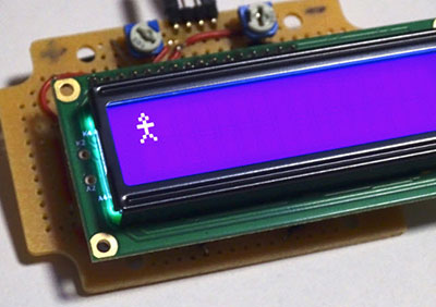
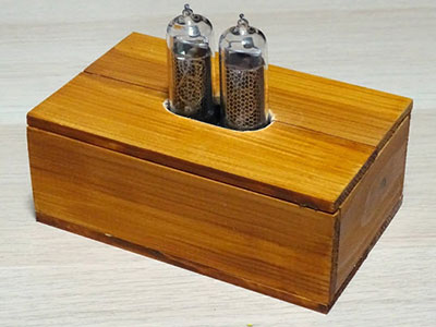
This image shows the finished device. I used five buttons to demonstrate how the display functions in its more complicated 4-bit mode.
BOM
Part/Qty
16x2 Character LCD - 1
10K Potentiometer - 1
SPDT Switches - 5
SPST Button - 1
1K Resistor - 1
10K Resistor - 1
Project Box - 1
Designing the Circuit
This project uses the HD44780’s 4-bit communication mode. Implementing the circuit in this way requires fewer components and space. Further, it also demonstrates how the more complicated model works and how you can switch the display from accepting a single 8-bit command to expecting two consecutive 4-bit commands instead. I’ll discuss the process of switching modes in more detail below. However, let’s focus on the schematic diagram for now:
This image contains the schematic diagram of this project.
Even though the schematic might look complicated at first, you should quickly see that it is very similar to a project that would contain an MCU to control the display.
First, this project uses a standard potentiometer so that users can tweak the display’s contrast. Then, five switches replace the MCU input lines. Note that the four data switches interface the display’s four most significant bit inputs. Connect the other inputs (D4-D0) to ground (GND) to permanently pull them low.
Note: I used single-pole double-throw (SPDT) switches to make the project easier to assemble. Using these switches, you can directly connect one input to GND and the other to the +5V line. If you decide to use single-pole single-throw (SPST) switches, you’ll have to include a pull-down resistor on each input line.
Lastly, a simple SPST push-button replaces the MCU’s enable signal that tells the display to latch the input data. However, since this is an SPST switch, you’ll have to add a resistor that pulls the display’s EN input low when the button is not pushed. The two resistors and the capacitor ensure that the input remains low until a user presses the button. However, these components simultaneously act as a simple hardware debounce measure so that the display receives a single enable signal when the user pushes the button. Without these components, a single button push could trigger the EN line to quickly alternate between LOW and HIGH multiple times due to the button’s contacts bouncing, which would cause unwanted behavior, such as repeated characters.
Assembling the Project
Start by cutting out a hole that matches the display size. You can either use a sharp knife to carefully create a cutout or a rotary tool, for example, a Dremel, for a cleaner-looking result. Next, use some masking tape and map out the positions of your input switches, the button, and the potentiometer:
This image shows the build process. I have already created a cutout for the display. Then, I used masking tape and a pen to lay out the inputs. Note that I used rectangular switches in my build. However, creating rectangular cutouts for each switch takes a long time, and you may be better off using round switches that only require you to drill some holes.
As you can see in the image above, I chose rectangular switches for this build. Creating five rectangular cutouts requires more effort than drilling five holes for the input switches. Therefore, I recommend you use simple round rocker switches instead or design and 3D print a custom enclosure. Either way, make sure to drill a small hole in the back of the enclosure so you can route a wire through the hole to supply the circuit with power. Also, don’t forget to drill four screw holes to mount the display.
Once you’re done creating the necessary holes and cutouts, it’s time to add the components to the project box. Use the nuts and washers that come with the switches to mount them to the enclosure. In my case, the switches just snap into place:
Use the supplied mounting hardware to attach the components to the case. Don’t forget to use four 1/10 inch (2.5mm) screws to secure the display.
Lastly, run wires from the switches to the appropriate inputs of the display. Pay close attention to the order in which you connect the switches. Remember that the device is flipped over while you’re attaching the wires, which makes it easy to connect the switches in the wrong order by accident.
Setting up the Device
As mentioned above, a previous article discussed the HD44780 communication protocol and commands in great detail, so I won’t go over the details in this article. Instead, let’s look at how to get the device to operate in 4-bit mode and how to send character data to the display.
Start by flipping all the switches to their off position before supplying the device with power. It’s normal that the screen displays all pixels when you first turn on the device because you need to run through the initialization steps that let the controller know which mode and font to use and how large the display is. Start by setting the display to 4-bit mode by sending the following command:
Set the switches as shown in this image to activate the LCD controller’s 4-bit mode.
Remember that at this point, the display still operates in 8-bit mode, which means that you’re sending the following command to the LCD controller:
0010 0000
Next, you need to set the font and the display size, which can be done with the following input sequence:
0010 1000
However, at this point, the display already operates in 4-bit mode. Therefore, you need to send the eight bits in two steps. First, set the switches to send the four most significant bits (0010). Then, press the EN button once. Next, set the controls to reproduce the next four bits (1000) and press the EN button again. Make sure that you leave the RS line low during this procedure. When done correctly, the previously displayed characters should disappear from the screen.
Next, activate the display, turn on the cursor, and make it blink by setting the following sequence like before:
0000 1111
Remember that you can refer to the previous article to learn more about the commands and possible parameters. Either way, the display should show a blinking cursor in the top-left corner once you're done. You can send the following command to clear the display should it show any garbage characters after this step:
0000 0000
Sending Character Data to the Display
When the RS switch is low, the display expects to receive control commands, such as the ones for clearing the display or setting the font. Flick the RS switch to HIGH to enter character data. Then, use the ASCII to binary conversion table showing printable characters at the end of this article to find the binary representation of a character you want to enter and input the bits in two 4-bit nibbles, as demonstrated above. For example, the binary representation of an upper-case D is as follows:
0100 0100
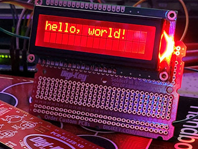
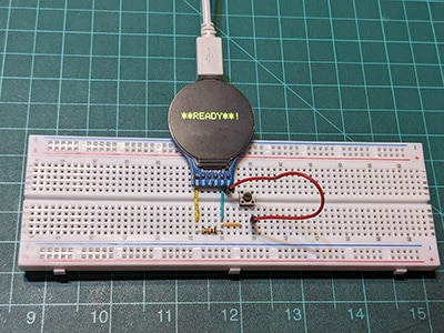
Repeat this procedure for all the characters you want to enter. Eventually, you’ll be able to spell out words:
Use the switches to input the binary values of the ASCII characters you want to send to the display.
Summary
This simple project allows you to directly interact with a standard 16x2 character LCD as it’s commonly used in DIY projects as well as commercial products. The schematic is quite simple and using SPDT switches allows you to further simplify the build process. Four of the five switches act as data inputs to the display, and the fifth switch selects the LCD controller’s register. A simple debounce measure ensures that the display controller doesn’t misinterpret a single button press as multiple consecutive presses.
Assembling the project is also not too complicated when working with suitable components. I recommend choosing round switches, as creating five rectangular cutouts for rocker switches can become quite time-consuming. You can use a Dremel or a similar rotary tool to create a cleaner cutout for the display. Lastly, remember to pay close attention when connecting the switches to the LCD to attach them in the correct order.
You have to repeat a simple setup procedure whenever you connect the device to power. This procedure sets the display to operate in 4-bit mode and then initializes it by selecting the display size and font. Next, activate the display and clear it before you can transmit character data. Finally, use the below ASCII to binary conversion table to find the binary values of standard printable characters.