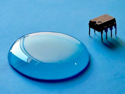
Mfr Part # AP63203WU-7
IC REG BUCK 3.3V 2A TSOT23-6
Diodes Incorporated
License: General Public License 3D Printing Current Voltage Regulators ESP32
converter,Disclaimer: This DIY project is for educational and experimental purposes only and is not intended to diagnose, treat, or prevent any medical condition. It involves electronic components that carry electrical current, which can be hazardous if handled incorrectly. Use caution and, at your own risk, follow proper safety practices and consult a qualified professional if you have any health concerns.
In part 1, we discussed how treating hyperhidrosis with an iontophoresis machine is costly for consumers. My goal was to alleviate the financial burden and create an open-source project that allows individuals to make their own treatment machine. We left off on some prototypes using the Phase Dock WorkBench and will continue by taking what we learned and designing our own custom PCB.
Phase 1: PCB Design
The changes made in this phase are as follows:
Using an optocoupler between the op-amp and the ESP32 to ensure the battery cannot interact directly with the patient.
Using relays instead of the H-bridge module. This also isolates the patient from the battery.
Changing the XL6019 boost module for an Ag7200 isolated DC-DC Converter, with an input-output isolation of 1500 volts. This is also a safety measure to further isolate the patient.
Replaced the LM7805 with the AP63203WU 3.3V switching regulator to increase the efficiency of the system
Using 4mm shrouded banana jacks for the electrode connections.
A 50mA quick-blow fuse in series with the relays, offering a fail-safe if something were to go wrong.
This would ideally be a compact design that offers safety features and a user-friendly interface. I used KiCAD to create the schematic and to lay out the PCB. Here is what the schematic looked like:
To maintain a compact design, I opted for a 6-layer PCB. This allowed me a little bit more flexibility in placing components and also made it easier to isolate the battery side from the treatment side.
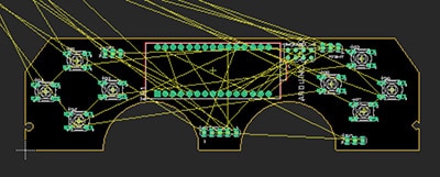
Here is the completed layout:
All six layers from left to right.
Signal layers are on the 1st and 6th layers, with power layers on the layers in between.
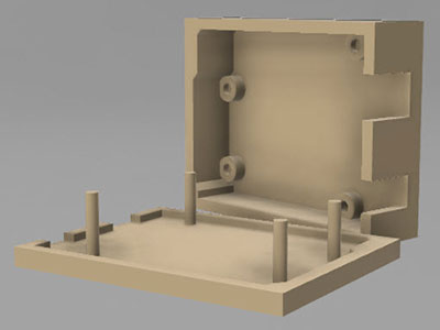
Phase 2: CADing a case for the device
My CAD of choice is Onshape, which is cloud-based software, but it delivers a smooth experience without having to run any programs on your computer. It’s pretty simple to export a PCB from KiCAD, which was the basis of my case design.
I designed the case to snap shut – definitely not the best in the interest of being water-resistant. The user assumes all risks when using this device (for now).
There is a charging port on the right-hand side and two 4 mm banana jacks for the electrodes. Those of you with a keen eye may have noticed a USB-C that doesn’t have a hole in the case; that’s simply for flashing the code onto the device before putting it together.
You’ll also notice a small tab on the right-hand side; this is to make opening the case a lot less painful for your fingernails.
Phase 3: Putting it all together
For assembly, the user will need to 3D print the case and order a PCB. The user will also need to order all the required components for the project and the M3 mounting screws required to attach the board to the case.
The user will need to order / create the following components:
All the components on this list
4x M3 mounting screws
1x 2000mAh rechargeable Li-Ion battery with charger
A conductive electrode that sits in the bin (the user must not be in contact with this)
Sponge material that blocks direct contact (ex. this) (prevents the user from touching the electrode)
1 or 2x plastic basins to hold water
Instructions for Use
The electrodes will need to be attached to the case via the shrouded banana jacks, with the other end clipped to the electrodes sitting in the water bins. Ensure a non-conductive mesh is placed over the conductive electrodes. Your skin should never make contact with the electrodes to prevent burns.
Treatment:
Configure your target current and treatment time using the built-in buttons and menu. Press Enter on ‘OK’ to confirm your settings and begin treatment. Halfway through the treatment, the device will switch the direction of the current by switching the relays. This ensures both limbs are treated equally. When the device says it’s finished, or when the current reads 0mA, the user can comfortably remove themselves from the water bins.
Phase 4: Planning ahead
Looking ahead, as this project is coming to a close, I will open-source all of the layout files and software. If someone looking for a project is inspired by this, they are encouraged to contribute.
https://github.com/apotatoa/Iontophoresis-Device/
Issues for a later date:
Since this device is battery-powered, efficiency is of utmost importance. It would be better to regulate the boost voltage rather than to drop the voltage across the MOSFET in order to regulate current. This is fundamentally a different approach than what this project was designed for, but it may be worth the effort for a better product.
The screen used in this design is a 0.96” OLED display, which looks very small in comparison with the case. To make the user experience better and make the screen more legible, increasing the size to 1.54” or larger would be a good change.
A huge thank you to Chris and Barbara Lehenbauer from Phase Dock for enabling me to work on this project. I could not have done this without your support.
Thank you for reading!
Bonus: Blender Render