Mfr Part # ESP32-S3-DEVKITC-1-N8R8
ESP32-S3-WROOM-1-N8R8 DEV BRD
Espressif Systems
License: General Public License Current Voltage Regulators ESP32
Disclaimer: This DIY project is for educational and experimental purposes only and is not intended to diagnose, treat, or prevent any medical condition. It involves electronic components that carry electrical current, which can be hazardous if handled incorrectly. Use caution and at your own risk, follow proper safety practices, and consult a qualified professional if you have any health concerns.
The problem: The $1000 treatment
My goal: To design a device to treat hyperhidrosis for a fraction of the retail price. Making treatment more accessible to patients while still meeting safety requirements.
The idea started forming after learning about hyperhidrosis and its treatment from people with the condition. The device they used cost about $1000!! After some quick research, I was confident a solution could be made for just a fraction of the price.
The process of treating hyperhidrosis is called iontophoresis. It’s not quite known exactly what the treatment does; it either disrupts normal nerve signals that tell your body to sweat or the ions produced by this process physically block the sweat duct. Doing this repeatedly on your hands, feet, or armpits will help treat the excessive sweating on those body parts.
My hope was to design and develop an iontophoresis device that was safe but much more affordable than retail solutions.
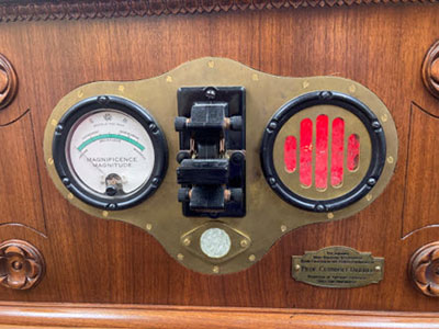
Some examples:
The Fischer
https://fischermedicalsupply.com/products/the-fischer-3-in-1
Dermadry Total
https://dermadry.com/products/dermadrytotal
Phase 1: Theory and Simulation
Before assembling the device, we need to learn about the requirements we need to meet and the design constraints we are working with. After some research, here is an initial list I came up with:
The user sets treatment time up to 20 minutes
Regulate a user-set current that travels through the body. Controlled by DAC voltage or similar through the op-amp and MOSFET
Dry human skin can exceed 1kΩ, but can drop below 300Ω in water
This means 30Vdc will give 30mA at 1kΩ
Current through skin must not exceed 30mA under any circumstances
Additional considerations are needed, such as how do we transport the electricity to the patient?
Plastic bins to hold tap/mineral water
Connectors that are able to be used safely in the presence of water
A way to safely move the electricity into the water and through the user
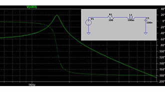
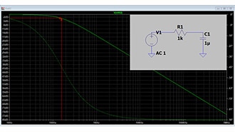
Seen below are a series of PSPICE simulations to help guide my process into prototyping. These simulations made it clear how I was going to build the current regulation portion of the circuit.
Circuit used in PSPICE for subsequent simulations
The proof-of-concept circuit used in PSPICE
Current across human skin when 30mA is selected
As the resistance of human skin goes up, it is clear that 1kΩ is the limit for a 30Vdc supply
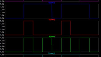
Sweeping Vset 0 - 300mV
I noticed there was a small discrepancy between the selection voltage and the output current, e.g 300mV was slightly below 30mA
Sweeping sense resistance from 0 to 20Ω by a step of 0.5Ω
There is a huge change in current as the resistance changes! For consistency’s sake, I decided to use 0-3V as the voltage select and switch to a 100Ω sense resistor. Greatly reducing error.
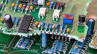
But that’s not all. We also need to be concerned with organization in our prototypes!
Phase 2: Prototyping on the WorkBench
This project was enabled by the Phase Dock WorkBench platform, as I interned with them during the summer of 2025. A photo of this WorkBench platform can be seen below; it enables students, hobbyists, and engineers to be more organized in the prototyping and speeds up the process considerably. You can learn more about them here https://www.digikey.com/en/supplier-centers/phase-dock-inc
After these simulations, it was time to start implementing.
To-do list:
Boost voltage 30-40Vdc
H-bridge to allow current to travel in both directions across the patient
Regulate current
Human input controller, timer, and current settings
Display and buttons
I started prototyping using the Phase Dock WorkBench, which led to these evolving prototypes:
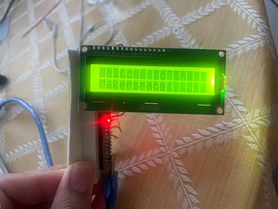
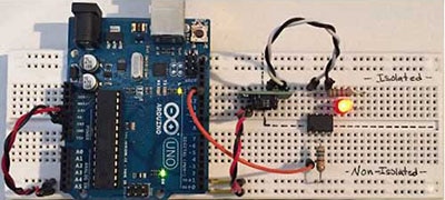
MCU interface with an OLED display
Shows a basic menu using an I2C-driven display and 3 buttons hooked up to GPIOs
Changed: +ESP32, +Display, +buttons
Battery and boost module in place, Phase Dock Clicks being used!
Preliminary battery setup and a speaker. The boost module and H-bridge are in place.
Changed: Rearranged user interface to be on one board, +DRV8871, +XL6019, +LM7805, +speaker
New battery, more seamless connections, buzzer.
A buzzer replaces the speaker, and a rechargeable battery replaces the AA pack.
Changed: +2000mAh LiPo
Current regulation circuit in place
The DRV8871 H-Bridge module caused the demise of two microcontrollers and added current regulation.
Changed: +LM7805 Heatsink, +Low-pass filter to smooth PWM signal, +IRFZ46NL Mosfet, +LM358 Opamp
I saw the advantages in using the Phase Dock WorkBench through these iterations. So much time was saved during the prototyping phase simply because I could just move Clicks around and not worry about having to reconstruct anything else. It was simply plug-and-play (or click-and-play, if you will) for most of this phase.
A few issues with the prototypes above:
The DRV8871 H-bridge IC wasn’t fully reliable in our implementation and actually ended up being the cause of an ESP32’s demise.
The XL6019 did not isolate the user from the battery, a cause for concern.
Changes to make for the final version:
Switch to a new H-bridge design using relays to control current direction
Replace the boost converter with an isolated boost converter
Switch the linear 5V regulator with a 3.3V switching regulator
This will directly power the esp32 and user peripherals
Add an optocoupler between the ESP32's PWM pin and the op-amp input.
Further isolates the user from the battery
Adding an electrode connector, 4mm shrouded banana jacks
50mA quick-blow fuse in series with the patient as a failsafe
Stay tuned for Part 2!
I’ll be going over the final iteration of this device, including PCB schematic design and layout, and 3D CADing a custom case to house all of the components.