Mfr Part # A000066
ARDUINO UNO R3 ATMEGA328P BOARD
Arduino
License: Apache License, Version 2.0 LoRa Arduino
As the Internet of Things (IoT) continues to grow, the need for reliable long-distance wireless communication with minimal power consumption has become increasingly important. Common wireless technologies such as Wi-Fi, Bluetooth, cellular networks, and traditional RF modules are widely used, but each comes with practical limitations. Wi-Fi and Bluetooth are designed for short-range communication and consume significant power, making them unsuitable for battery-operated IoT devices. Cellular networks offer wide coverage but are expensive to deploy and operate, while also drawing considerable power. Conventional RF modules can transmit over longer distances but often require higher transmission power and a complex configuration.
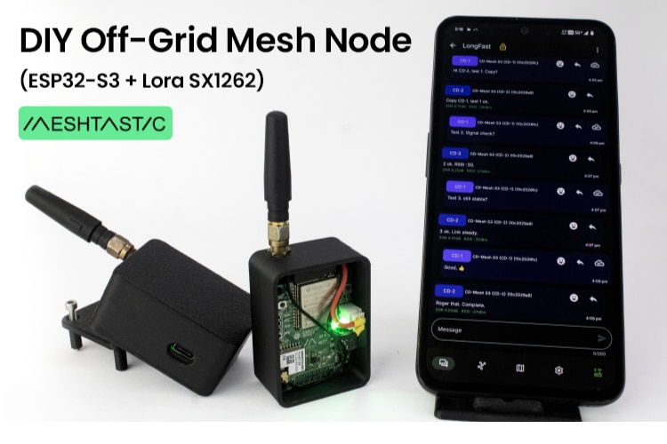
To overcome these challenges, LoRa (Long Range) technology was developed. LoRa enables devices to communicate over several kilometers while consuming extremely low power, making it ideal for IoT applications such as environmental monitoring, smart agriculture, asset tracking, and industrial sensing. In this guide, we will learn how to interface the RYLR999 LoRa module with an Arduino.
LoRa, which stands for Long Range, is a wireless communication technology developed by Semtech specifically for low-power, long-distance data transmission. Unlike Wi-Fi or Bluetooth, which are optimized for high data rates over short distances, LoRa is designed for devices that transmit small amounts of data over long distances while operating on battery power for months or even years.
LoRa is particularly well-suited for IoT devices that periodically send sensor data such as temperature, humidity, water levels, motion alerts, or system status messages. Under ideal open-area conditions, LoRa communication can achieve ranges of 15 to 20 kilometers. It operates in license-free ISM frequency bands, commonly 433 MHz, 868 MHz, or 915 MHz, depending on regional regulations. For applications that require higher data throughput, LoRa can also operate in the 2.4 GHz band, although this reduces the effective range.
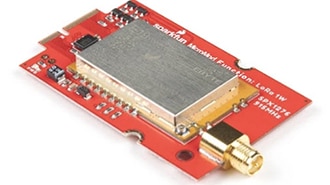
The RYLR999 Lite is a versatile long-range wireless communication module developed by REYAX Technology. What makes this module particularly powerful is its dual capability—it combines LoRa communication at 868/915 MHz with 2.4 GHz Bluetooth Low Energy (BLE) in a single compact module. This design allows both short-range and long-range wireless communication to coexist on the same hardware.
The module provides separate UART interfaces for LoRa and BLE, enabling independent control of each communication channel. The BLE UART interface is used for communication with smartphones, BLE-enabled microcontrollers, or other BLE devices, while the LoRa UART interface is dedicated to long-range data transmission.
All configuration parameters—including device address, network ID, frequency, transmission power, and modulation settings—are managed using simple AT commands. When a transmission command is issued, the RYLR999 modulates the data using LoRa’s CSS technique and transmits it over long distances. A receiving RYLR999 module demodulates the packet and outputs the received data through its UART interface.
The RYLR999 module uses a simple pin configuration for power and UART communication.
VDD pin: supplies power to the module and must be connected to a regulated 5V source within the range of 4.75V to 5.25V.
GND pin: It is the ground pin.
RST pin: An active-low reset pin; pulling this pin to logic LOW resets the module.
TXD_LoRa: It is a LoRa UART transmit pin.
RXD_LoRa: It is used for receiving data over the LoRa UART interface.
TXD_BLE and RXD_BLE: These pins are used for UART communication with the BLE subsystem. These pins are essential when the module is used for BLE-to-LoRa bridging.
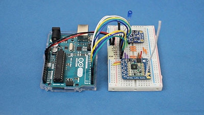
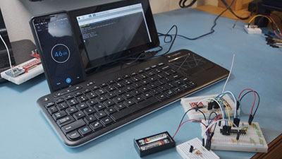
To demonstrate practical LoRa communication, a simple point-to-point setup is created using two Arduino UNO boards and two RYLR999 modules. One Arduino acts as the initiator, periodically transmitting a message, while the second Arduino acts as the responder, listening for incoming messages and replying accordingly. This two-way exchange verifies that LoRa communication is functioning correctly.
Before writing the code, it is important to understand how the RYLR999 modules are wired to the Arduino boards on both sides.
Components Required
LCD 16x2
Arduino UNO R3
Jumper Wires
USB Cable Type A to B
12V Supply Adapter
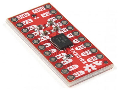
5V Voltage Shifter Module
2 RYLR999 Modules
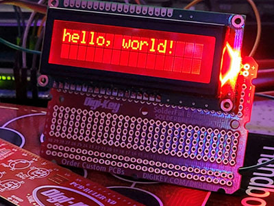
In the initiator setup, the Arduino UNO sends AT commands to the RYLR999 module and displays transmission status on a 16×2 I2C LCD. The VDD pin of the RYLR999 is connected to the Arduino’s 5V output, and the GND pin is connected to the Arduino’s ground to establish a common reference.
Since the Arduino UNO operates at 5V logic levels and the RYLR999 uses 3.3V UART logic, a bi-directional voltage level shifter is required. The TXD_LoRa pin of the RYLR999 is connected to the low-voltage (LV1) side of the voltage shifter, and the corresponding high-voltage (HV1) output is connected to the Arduino’s RX pin. Similarly, the Arduino’s TX pin is connected to the HV2 side of the voltage shifter, and the corresponding LV2 output is connected to the RXD_LoRa pin of the RYLR999.
To power the voltage shifter correctly, the Arduino’s 5V pin is connected to the HV supply pin of the level shifter, and the Arduino’s 3.3V pin is connected to the LV supply pin. These power connections ensure safe and reliable voltage translation between the Arduino and the LoRa module.
The I2C LCD is wired by connecting its VCC and GND pins to the Arduino’s 5V and GND. The LCD’s SDA and SCL pins are connected to the Arduino’s SDA (A4) and SCL (A5) pins. Care must be taken to ensure that the address jumpers on the back of the I2C LCD are not shorted, as the code uses the default I2C address 0x27, which corresponds to all address jumpers being open.
The responder setup is simpler because it does not include an LCD. The Arduino UNO continuously listens for incoming LoRa messages from the RYLR999 module and responds when a valid message is received. The power and UART wiring between the Arduino and the RYLR999 module remain identical to the initiator setup, including the use of a voltage level shifter to protect the 3.3V logic pins of the LoRa module.
With both initiator and responder correctly wired, the system is ready for programming and testing, demonstrating reliable long-range, low-power wireless communication using LoRa technology.
/*
Code to send “Are you there?” from one Arduino to another Arduino using RLYR999 Module
and receive reply and display complete communication on I2C LCD by platwithcircuit.com
*/
#include <LiquidCrystal_I2C.h>
#define REPLY_TIMEOUT_IN_MS 300
#define REPLY_END_CHAR '\n'
#define MODULE_ADDRESS 0
#define RECEIVERS_ADDRESS 1
#define MIN_CHAR_TO_RCV 1
#define WAIT_FOR_RECIVERS_REPLY 3000
#define DELAY_BW_REPS 1000
// Init LCD at 0x27, 16x2
LiquidCrystal_I2C lcd(0x27, 16, 2);
void setup() {
  boolean boRetVal = false;
  // begin serial communication at baud 115200,n,8,1
  // to communicate with the RF module
  Serial.begin(115200);
  // initialize the LCD
  lcd.init();
  // Turn ON the Backlight
  lcd.backlight();
  // Clear the display buffer
  lcd.clear();
  flushBuffer();  // clear rx data
  // Reset settings to factory defaults
  boRetVal = boRestoreFactoryDefaults();
  // setting the address if reset successfully
  if (boRetVal == true) {
    flushBuffer();  // clear rx data
    boRetVal = boSetAddress();
  }
  if (boRetVal == true) {
    lcd.clear();
    lcd.setCursor(0, 0);
    lcd.print("Module Init");
    lcd.setCursor(0, 1);
    lcd.print("Successful");
    delay(1000);
  } else {
    lcd.clear();
    lcd.setCursor(0, 0);
    lcd.print("Module Init");
    lcd.setCursor(0, 1);
    lcd.print("Failed");
    while (1)
      ;
  }
}
void loop() {
  String request = "Are you there?";
  String expected_reply = "Yes";
  bool boRetVal = false;
  flushBuffer();  // clear rx data
  // transmits String named request
  boRetVal = boSendData(request);
  if (boRetVal == true) {
    // Displaying Sent Msg
    lcd.clear();
    lcd.setCursor(0, 0);
    lcd.print("Msg Sent:");
    lcd.setCursor(0, 1);
    lcd.print(request);
    delay(1000);
    boRetVal = chkReply(expected_reply, REPLY_END_CHAR, WAIT_FOR_RECIVERS_REPLY);
    if (boRetVal == true) {
      // Displaying received Msg
      lcd.clear();
      lcd.setCursor(0, 0);
      lcd.print("Msg Received:");
      lcd.setCursor(0, 1);
      lcd.print(expected_reply);
    } else {
      lcd.clear();
      lcd.setCursor(0, 0);
      lcd.print("No reply received.");
    }
  } else {
    // Displaying Failed Msg
    lcd.clear();
    lcd.setCursor(0, 0);
    lcd.print("Msg Sending");
    lcd.setCursor(0, 1);
    lcd.print("Failed");
  }
  delay(DELAY_BW_REPS);  // wait before sending again
}
void sendCrLf(void) {
  Serial.write(0x0D);  // Carriage Return
  Serial.write(0x0A);  // Line Feed
}
void flushBuffer(void) {
  while (Serial.available() > 0) {
    Serial.read();
  }
}
bool chkReply(String chkString, char receiveUntil, unsigned int timeout) {
  String receivedString;       // save received data in this string object
  bool boReturnValue = false;  // function's return value
  // wait for reply
  do {
    timeout--;
    delay(1);  // delay of 1 ms
  } while ((Serial.available() < MIN_CHAR_TO_RCV) && (timeout > 0));
  if (timeout) {
    // if timeout is left then a reply is received check for the string in the reply
    receivedString = Serial.readStringUntil(receiveUntil);
    if (receivedString.indexOf(chkString) != -1) {
      boReturnValue = true;
    } else {
      boReturnValue = false;
    }
  } else {
    boReturnValue = false;
  }
  // return result
  return boReturnValue;
}
bool boRestoreFactoryDefaults(void) {
  const char factoryDefaultCmd[] = "AT+FACTORY";  // command to be sent
  bool boReturnValue = false;                     // function's return value
  char downCounter = 100;                         // Down counter to wait for reply
  String receivedString;                          // save received data in this string object
  String chkRcvString1 = "+FACTORY";
  String chkRcvString2 = "+READY";
  // send command
  Serial.print(factoryDefaultCmd);
  sendCrLf();
  // check first string in reply
  boReturnValue = chkReply(chkRcvString1, REPLY_END_CHAR, REPLY_TIMEOUT_IN_MS);
  if (boReturnValue == true) {
    // check second string in reply
    boReturnValue = chkReply(chkRcvString2, REPLY_END_CHAR, REPLY_TIMEOUT_IN_MS);
  }
  // return result
  return boReturnValue;
}
bool boSetAddress(void) {
  const char setAddressCmd[] = "AT+ADDRESS=";  // command to be sent
  bool boReturnValue = false;                  // function's return value
  String chkRcvString = "+OK";
  // send command
  Serial.print(setAddressCmd);
  Serial.print(MODULE_ADDRESS);
  sendCrLf();
  // check reply
  boReturnValue = chkReply(chkRcvString, REPLY_END_CHAR, REPLY_TIMEOUT_IN_MS);
  // return result
  return boReturnValue;
}
bool boSendData(String data) {
  const char sendDataCmd[] = "AT+SEND=";  // command to be sent
  bool boReturnValue = false;             // function's return value
  String chkRcvString = "+OK";
  // send command
  Serial.print(sendDataCmd);
  Serial.print(RECEIVERS_ADDRESS);
  Serial.print(',');
  Serial.print(data.length());
  Serial.print(',');
  Serial.print(data);
  sendCrLf();
  // check reply
  boReturnValue = chkReply(chkRcvString, REPLY_END_CHAR, REPLY_TIMEOUT_IN_MS);
  // return result
  return boReturnValue;
}/*
Code to receive “Are you there?” from one Arduino to another Arduino using RLYR999 Module
and send "Yes" in reply by platwithcircuit.com
*/
#include <LiquidCrystal_I2C.h>
#define REPLY_TIMEOUT_IN_MS 300
#define REPLY_END_CHAR '\n'
#define MODULE_ADDRESS 1
#define RECEIVERS_ADDRESS 0
#define MIN_CHAR_TO_RCV 1
#define WAIT_FOR_REQUEST 3000
void setup() {
boolean boRetVal = false;
// begin serial communication at baud 115200,n,8,1
// to communicate with the RF module
Serial.begin(115200);
delay(1000);
flushBuffer(); // clear rx data
// Reset settings to factory defaults
boRetVal = boRestoreFactoryDefaults();
// setting the address if reset successfully
if (boRetVal == true) {
flushBuffer(); // clear rx data
boRetVal = boSetAddress();
}
if (boRetVal != true) {
Serial.print("\n\rModule Init");
Serial.print("Failed");
while (1)
;
}
}
void loop() {
String request = "Are you there?";
String expected_reply = "Yes";
bool boRetVal = false;
// check string sent by Initiator
boRetVal = chkReply(request, REPLY_END_CHAR, WAIT_FOR_REQUEST);
if (boRetVal == true) {
boSendData(expected_reply);
}
}
void sendCrLf(void) {
Serial.write(0x0D); // Carriage Return
Serial.write(0x0A); // Line Feed
}
void flushBuffer(void) {
while (Serial.available() > 0) {
Serial.read();
}
}
bool chkReply(String chkString, char receiveUntil, unsigned int timeout) {
String receivedString; // save received data in this string object
bool boReturnValue = false; // function's return value
// wait for reply
do {
timeout--;
delay(1); // delay of 1 ms
} while ((Serial.available() < MIN_CHAR_TO_RCV) && (timeout > 0));
if (timeout) {
// if timeout is left then a reply is received check for the string in the reply
receivedString = Serial.readStringUntil(receiveUntil);
if (receivedString.indexOf(chkString) != -1) {
boReturnValue = true;
} else {
boReturnValue = false;
}
} else {
boReturnValue = false;
}
// return result
return boReturnValue;
}
bool boRestoreFactoryDefaults(void) {
const char factoryDefaultCmd[] = "AT+FACTORY"; // command to be sent
bool boReturnValue = false; // function's return value
char downCounter = 100; // Down counter to wait for reply
String receivedString; // save received data in this string object
String chkRcvString1 = "+FACTORY";
String chkRcvString2 = "+READY";
// send command
Serial.print(factoryDefaultCmd);
sendCrLf();
// check first string in reply
boReturnValue = chkReply(chkRcvString1, REPLY_END_CHAR, REPLY_TIMEOUT_IN_MS);
if (boReturnValue == true) {
// check second string in reply
boReturnValue = chkReply(chkRcvString2, REPLY_END_CHAR, REPLY_TIMEOUT_IN_MS);
}
// return result
return boReturnValue;
}
bool boSetAddress(void) {
const char setAddressCmd[] = "AT+ADDRESS="; // command to be sent
bool boReturnValue = false; // function's return value
String chkRcvString = "+OK";
// send command
Serial.print(setAddressCmd);
Serial.print(MODULE_ADDRESS);
sendCrLf();
// check reply
boReturnValue = chkReply(chkRcvString, REPLY_END_CHAR, REPLY_TIMEOUT_IN_MS);
// return result
return boReturnValue;
}
bool boSendData(String data) {
const char sendDataCmd[] = "AT+SEND="; // command to be sent
bool boReturnValue = false; // function's return value
String chkRcvString = "+OK";
// send command
Serial.print(sendDataCmd);
Serial.print(RECEIVERS_ADDRESS);
Serial.print(',');
Serial.print(data.length());
Serial.print(',');
Serial.print(data);
sendCrLf();
// check reply
boReturnValue = chkReply(chkRcvString, REPLY_END_CHAR, REPLY_TIMEOUT_IN_MS);
// return result
return boReturnValue;
}
Code Explanation
Here the setup function has the same initialization steps as explained in the code for initiator, including serial communication setup, factory reset, and address configuration. The main difference is that the responder does not use an LCD and reports errors only through the serial monitor.
void setup() {
boolean boRetVal = false;
// begin serial communication at baud 115200,n,8,1
// to communicate with the RF module
Serial.begin(115200);
delay(1000);
flushBuffer(); // clear rx data
// Reset settings to factory defaults
boRetVal = boRestoreFactoryDefaults();
// setting the address if reset successfully
if (boRetVal == true) {
flushBuffer(); // clear rx data
boRetVal = boSetAddress();
}
if (boRetVal != true) {
Serial.print("\n\rModule Init");
Serial.print("Failed");
while (1)
;
}
}