Mfr Part # 5889
ADAFRUIT ITSYBITSY ESP32 - PCB A
Adafruit Industries LLC
License: See Original Project Wifi ESP32
Courtesy of Adafruit
Guide by John Park
Overview
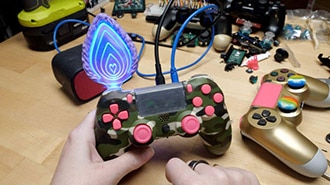
The original PlayStation controller is great, but it's wired for use with a PlayStation. This guide shows how to cut the cord and convert it to a wireless Bluetooth gamepad for your computer gaming needs.
An Adafruit ItsyBitsy ESP32 and Arduino software make it all possible, and a LiPo battery and built-in charger keep it powered.
Parts
Adafruit ItsyBitsy ESP32 - PCB Antenna - 8 MB Flash / 2 MB PSRAM
Adafruit LiIon/LiPoly Backpack Add-On for Pro Trinket/ItsyBitsy
PlayStation Controller
Use an original Sony PlayStation controller model SCPH-1080 -- the kind before the dual analog sticks or rumble motors were added. These can be had for around $10 at a retro gaming store or online auction.
Arduino IDE Setup
You need to install the right USB-to-serial driver for your chip in addition to the Arduino IDE. If you are unsure which is the right one, install both!
Install Arduino IDE
The first thing you will need to do is to download the latest release of the Arduino IDE. You will need to be using version 1.8 or higher for this guide.
Install CP2104 / CP2102N USB Driver
The USB-to-Serial converter that talks to the ESP32 chip itself will need a driver on your computer's operating system. The driver is available for Mac and Windows. It is already built into Linux.
Click here to download the CP2104 USB Driver
Install CH9102 / CH34X USB Driver
Newer ESP32 boards have a different USB-to-serial converter that talks to the chip itself and will need a driver on your computer's operating system. The driver is available for Mac and Windows. It is already built into Linux.
If you would like more detail, check out the guide on installing these drivers.
Click here to download the Windows driver
Click here to download the Mac driver
Install ESP32 Board Support Package
After you have downloaded and installed the latest version of Arduino IDE, you will need to start the IDE and navigate to the Preferences menu. You can access it from the File menu in Windows or Linux, or the Arduino menu on OS X.
A dialog will pop up just like the one shown below.
We will be adding a URL to the new Additional Boards Manager URLs option. The list of URLs is comma separated, and you will only have to add each URL once. New Adafruit boards and updates to existing boards will automatically be picked up by the Board Manager each time it is opened. The URLs point to index files that the Board Manager uses to build the list of available & installed boards.
To find the most up to date list of URLs you can add, you can visit the list of third party board URLs on the Arduino IDE wiki. We will only need to add one URL to the IDE in this example, but you can add multiple URLS by separating them with commas. Copy and paste the link below into the Additional Boards Manager URLs option in the Arduino IDE preferences.
https://raw.githubusercontent.com/espressif/arduino-esp32/gh-pages/package_esp32_dev_index.json
If you have multiple boards you want to support, say ESP8266 and Adafruit, have both URLs in the text box separated by a comma (,)
Once done click OK to save the new preference settings.
The next step is to actually install the Board Support Package (BSP). Go to the Tools → Board → Board Manager submenu. A dialog should come up with various BSPs. Search for esp32.
Click the Install button and wait for it to finish. Once it is finished, you can close the dialog.
In the Tools → Board submenu you should see ESP32 Arduino and in that dropdown, it should contain the ESP32 boards along with all the latest ESP32 boards.
Look for the board called Adafruit ItsyBitsy ESP32.
The upload speed can be changed: faster speed makes uploads take less time but sometimes can cause upload issues. 921600 should work fine, but if you're having issues, you can drop down lower.
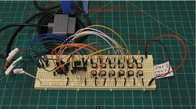
Controller Circuit
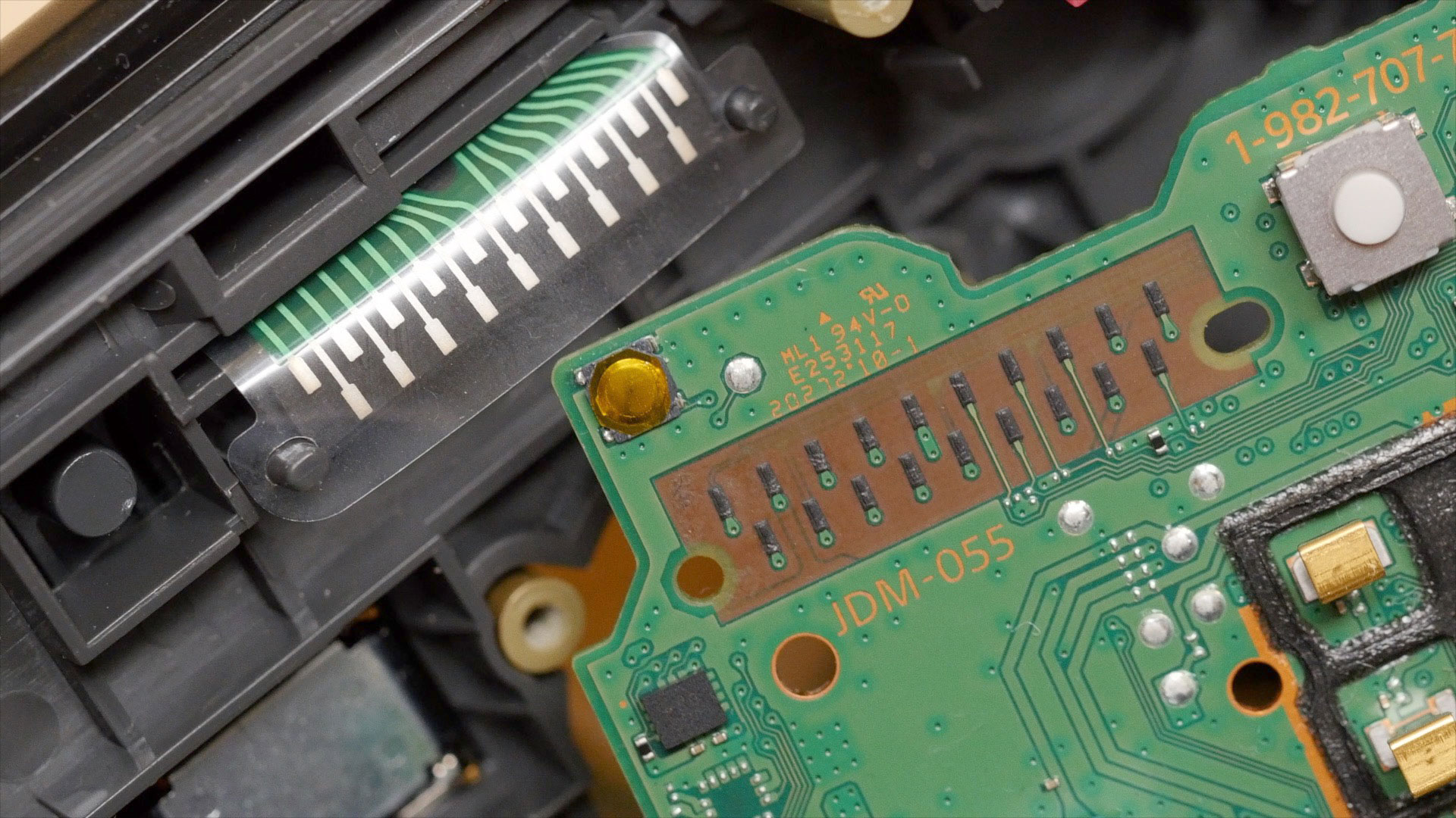
The PlayStation controller PCB uses conductive pads that short to ground when the buttons are pressed. Using a continuity tester, I diagrammed these traces, and the copper test points we will use to wire the buttons to the microcontroller.
You can see from the above diagrams that we'll wire up most of the PlayStation controller buttons to GPIO pins on the ItsyBitsy ESP32. The R2 trigger button will be wired to the Reset button, and the L2 is left unused. (You could choose to wire it and adjust the Arduino sketch if you like.)
Code the Controller
Copy the example below and paste it into the Arduino IDE.
You must change the ssid and password in the example code to your WiFi SSID and password before uploading this to your board. This is only necessary if you plan to use the over-the-air (OTA) update feature, otherwise you can leave these alone.
You can also change the sleepSeconds value if you want your controller to go into deep sleep sooner or later than the default 30 seconds.
Once you've made these changes, upload the code to your ItsyBitsy ESP32.
// SPDX-FileCopyrightText: 2024 John Park for Adafruit Industries
//
// SPDX-License-Identifier: MIT
/*
 * Feather ESP32 Bluetooth LE gamepad https://github.com/lemmingDev/ESP32-BLE-Gamepad
 * Deep sleep with wake on START button press
 * https://randomnerdtutorials.com/esp32-deep-sleep-arduino-ide-wake-up-sources/

 * OTA WiFi uploads
 * https://docs.espressif.com/projects/arduino-esp32/en/latest/ota_web_update.html
 * Sketch > Compile binary, then http://esp32.local/?userid=admin&pwd=admin
 * pick compiled .bin, upload.
 */

#include <Arduino.h>
#include <BleGamepad.h>
#include <Adafruit_NeoPixel.h>

#include <esp_wifi.h>
#include <WiFi.h>
#include <WiFiClient.h>
#include <WebServer.h>
#include <ESPmDNS.h>
#include <Update.h>

bool web_ota = false;

int sleepSeconds = 30; // how long is it inactive before going to sleep

const char* host = "esp32";
const char* ssid = "xxxxxxx";  // your WiFi SSID here
const char* password = "xxxxxxxx";  // your WiFi password here
WebServer server(80);

/*
 * Login page
 */

const char* loginIndex =
 "<form name='loginForm'>"
    "<table width='20%' bgcolor='A09F9F' align='center'>"
        "<tr>"
            "<td colspan=2>"
                "<center><font size=4><b>ESP32 Login Page</b></font></center>"
                "<br>"
            "</td>"
            "<br>"
            "<br>"
        "</tr>"
        "<tr>"
             "<td>Username:</td>"
             "<td><input type='text' size=25 name='userid'><br></td>"
        "</tr>"
        "<br>"
        "<br>"
        "<tr>"
            "<td>Password:</td>"
            "<td><input type='Password' size=25 name='pwd'><br></td>"
            "<br>"
            "<br>"
        "</tr>"
        "<tr>"
            "<td><input type='submit' onclick='check(this.form)' value='Login'></td>"
        "</tr>"
    "</table>"
"</form>"
"<script>"
    "function check(form)"
    "{"
    "if(form.userid.value=='admin' && form.pwd.value=='admin')"
    "{"
    "window.open('/serverIndex')"
    "}"
    "else"
    "{"
    " alert('Error Password or Username')/*displays error message*/"
    "}"
    "}"
"</script>";

/*
 * Server Index Page
 */

const char* serverIndex =
"<script src='https://ajax.googleapis.com/ajax/libs/jquery/3.2.1/jquery.min.js'></script>"
"<form method='POST' action='#' enctype='multipart/form-data' id='upload_form'>"
   "<input type='file' name='update'>"
        "<input type='submit' value='Update'>"
    "</form>"
 "<div id='prg'>progress: 0%</div>"
 "<script>"
  "$('form').submit(function(e){"
  "e.preventDefault();"
  "var form = $('#upload_form')[0];"
  "var data = new FormData(form);"
  " $.ajax({"
  "url: '/update',"
  "type: 'POST',"
  "data: data,"
  "contentType: false,"
  "processData:false,"
  "xhr: function() {"
  "var xhr = new window.XMLHttpRequest();"
  "xhr.upload.addEventListener('progress', function(evt) {"
  "if (evt.lengthComputable) {"
  "var per = evt.loaded / evt.total;"
  "$('#prg').html('progress: ' + Math.round(per*100) + '%');"
  "}"
  "}, false);"
  "return xhr;"
  "},"
  "success:function(d, s) {"
  "console.log('success!')"
 "},"
 "error: function (a, b, c) {"
 "}"
 "});"
 "});"
 "</script>";

////////////////////////////////////// GAMEPAD
#define numOfButtons 12
// sleep wake button definition (also update line in setup(): 'esp_sleep_enable_ext0_wakeup(GPIO_NUM_4,0);')
#define BUTTON_PIN_BITMASK 0x10 // start button on RTC GPIO pin 4 which is 0x10 (2^4 in hex)
// RTC_DATA_ATTR int bootCount = 0;

BleGamepad bleGamepad("ItsyController", "Adafruit", 100);  // name, manufacturer, batt level to start
byte previousButtonStates[numOfButtons];
byte currentButtonStates[numOfButtons];

// ItsyBitsy EPS32: 13, 12, 14, 33, 32, 7, 5, 27, 15, 20, 8, 22, 21, 19, 36, 37, 38, 4, 26, 25
// RTC IO: 13, 12, 14, 33, 32, 27, 15, 36, 37, 38, 4, 26, 25
// pins that act funny: 5, 37, 22
byte buttonPins[numOfButtons] =      { 13, 12, 14, 33, 32,  7,  27,  15,  21,  19,   4, 26 }; // ItsyBitsy
byte physicalButtons[numOfButtons] = {  1,  2,  4,  5,  7,  8,  15,  16,  13,  14,  12, 11 }; // controller assignments
//                                     b0, b1, b3, b4, b6, b7, b14, b15, b12, b13, b10, b11
// gampad: O/b0, X/b1, ^/b3, []]/b4, l_trig/b6, r_trig/b7, up/b14 , down/b15 , left/b12 , right/b13, select/b11, start/b10

int last_button_press = millis();
int sleepTime = (sleepSeconds * 1000);

Adafruit_NeoPixel pixel(1, 0, NEO_GRB + NEO_KHZ800);  // Itsy on-board NeoPixel

void setup()
{
  Serial.begin(115200);
  delay(500);

  //Print the wakeup reason for ESP32
  // print_wakeup_reason();
  esp_sleep_enable_ext0_wakeup(GPIO_NUM_4,0); //1 = High, 0 = Low

  for (byte currentPinIndex = 0; currentPinIndex < numOfButtons; currentPinIndex++)
  {
        pinMode(buttonPins[currentPinIndex], INPUT_PULLUP);
        previousButtonStates[currentPinIndex] = HIGH;
        currentButtonStates[currentPinIndex] = HIGH;
  }

  bleGamepad.begin();
  delay(100);
  pixel.begin();
  pixel.clear();

  if (web_ota) {

    // Connect to WiFi network
    WiFi.begin(ssid, password);
    Serial.println("");

    // Wait for connection for 20 seconds, then move on
    unsigned long startTime = millis(); // Get the current time
    while (!(WiFi.status() == WL_CONNECTED) && ((millis() - startTime) < 2000)) {
      delay(500);
      Serial.print(".");
    }

    if (WiFi.status() == WL_CONNECTED) {

      Serial.println("");
      Serial.print("Connected to ");
      Serial.println(ssid);
      Serial.print("IP address: ");
      Serial.println(WiFi.localIP());

      /*use mdns for host name resolution*/
      if (!MDNS.begin(host)) { //http://esp32.local
        Serial.println("Error setting up MDNS responder!");
        while (1) {
          delay(1000);
        }
      }
      Serial.println("mDNS responder started");
      /*return index page which is stored in serverIndex */
      server.on("/", HTTP_GET, []() {
        server.sendHeader("Connection", "close");
        server.send(200, "text/html", loginIndex);
      });
      server.on("/serverIndex", HTTP_GET, []() {
        server.sendHeader("Connection", "close");
        server.send(200, "text/html", serverIndex);
      });
      /*handling uploading firmware file */
      server.on("/update", HTTP_POST, []() {
        server.sendHeader("Connection", "close");
        server.send(200, "text/plain", (Update.hasError()) ? "FAIL" : "OK");
        ESP.restart();
      }, []() {
        HTTPUpload& upload = server.upload();
        if (upload.status == UPLOAD_FILE_START) {
          Serial.printf("Update: %s\n", upload.filename.c_str());
          if (!Update.begin(UPDATE_SIZE_UNKNOWN)) { //start with max available size
            Update.printError(Serial);
          }
        } else if (upload.status == UPLOAD_FILE_WRITE) {
          /* flashing firmware to ESP*/
          if (Update.write(upload.buf, upload.currentSize) != upload.currentSize) {
            Update.printError(Serial);
          }
        } else if (upload.status == UPLOAD_FILE_END) {
          if (Update.end(true)) { //true to set the size to the current progress
            Serial.printf("Update Success: %u\nRebooting...\n", upload.totalSize);
          } else {
            Update.printError(Serial);
          }
        }
      });
      server.begin();
    }
    else {
      Serial.println("");
      Serial.println("WiFi connection timed out, you may need to update SSID/password. Moving on now.");
    }
  }
}

void loop()
{
  if (web_ota) {
    server.handleClient();
    delay(1);
  }

  if (bleGamepad.isConnected())
  {
    pixel.setPixelColor(0, 0x000033);
    pixel.show();

    for (byte currentIndex = 0; currentIndex < numOfButtons; currentIndex++)
        {
            currentButtonStates[currentIndex] = digitalRead(buttonPins[currentIndex]);

            if (currentButtonStates[currentIndex] != previousButtonStates[currentIndex])
            {
                last_button_press = millis();  // update last_button_press for sleep timing

                if (currentButtonStates[currentIndex] == LOW)
                {
                    bleGamepad.press(physicalButtons[currentIndex]);
                }
                else
                {
                    bleGamepad.release(physicalButtons[currentIndex]);
                }
            }
        }

        if (currentButtonStates != previousButtonStates)
        {
            for (byte currentIndex = 0; currentIndex < numOfButtons; currentIndex++)
            {
                previousButtonStates[currentIndex] = currentButtonStates[currentIndex];
            }

            bleGamepad.sendReport();
        }
      if (millis() - last_button_press > sleepTime) {
          server.stop();
          delay(300);
          esp_wifi_stop();
          delay(300);
          esp_deep_sleep_start();
        }
    }
}Gamepad
You'll use the BleGamepad library to create the gamepad object:
BleGamepad bleGamepad("ItsyController", "Adafruit", 100); // name, manufacturer, batt level to start
You can pick your own string for the name, so in this case "ItsyController" will show up on your computer or other device during pairing. The battery level feature is not used in this project.
Deep Sleep
Deep sleep mode saves on battery consumption by turning off the ESP32's processor, WiFi and Bluetooth radios, while keeping the Ultra Low Power co-processor (ULP) active, checking for the wake-up call.
Wake up sources can include a timer, cap touch pin, and external sources, a.k.a. buttons. We'll use the PlayStation's start button as our wake-up source.
The way the code works is to keep track of when buttons are pressed and if none has been touched for thirty seconds (or whatever sleepTime you pick), the server and WiFi radio are stopped, and then esp_deep_sleep_start(); is called.
if (millis() - last_button_press > sleepTime) {
          server.stop();
          delay(300);
          esp_wifi_stop();
          delay(300);
          esp_deep_sleep_start();
        }
Wake Up
While in deep sleep, the ULP can keep an eye on any of the real time clock (RTC) GPIO pins. On the ItsyBitsy ESP32 this is any of the following pins: 13, 12, 14, 33, 32, 27, 15, 36, 37, 38, 4, 26, 25.
We'll use pin 4, which is the one the start button is connected to:
esp_sleep_enable_ext0_wakeup(GPIO_NUM_4,0);
The '0' indicates that wake up will happen when the indicated pin 4 goes low.
Web Update
If you want to update the code after you've closed up your controller, you can use the over-the-air (OTA) web update.
Point your browser at the ItsyBitsy's server at http://esp32.local and login with:
username = admin
password = admin
Follow the info in this guide on compiling and uploading your firmware.
Convert the Controller
These are the main steps you'll do for the conversion:
open up the controller
remove wired connector cable and the original IC
solder wires from the button test points to the ItsyBitsy ESP32
cut a little bit of plastic to fit the USB connector for charging
optionally, drill a couple of holes to see the status LEDs
Open the Controller
Unscrew the eight screws with a Philips #1 screwdriver and set them in a safe place.
Open the controller by lifting up the back shell.
Remove the main PCB and shoulder button boards, then set the case and rubber button pads aside.
LED Holes
You can drill a small hole if you like in the back of the case so you can see the indicator NeoPixel LED.
A hole in the inner side of the right grip in the back of the case can be used to see the charger LED status.
You could optionally get fancy and fashion some light pipes from clear plastic. The best bet is usually to scavenge light pipes from old, broken hardware.
Desolder Cable
Flip the PCB over and desolder the six pins that connect the cable to the PCB. It's helpful to use some extra flux or fresh solder, heat up each joint and then use a solder sucker to, well, suck up the solder.
You can also desolder and remove the large electrolytic capacitor to free up some space.
We'll use these holes for routing wires, so it's good to get them nice and free of solder.
IC Removal
This is also a good time to desolder and remove the original IC controller chip from the PCB.
You can see from these pictures that I had already wired the buttons pads when I realized the IC needed to be removed, otherwise I was seeing spurious button presses occur as the IC was being accidentally powered in unintended ways.
Wiring
This is the most fiddly part. Wiring the buttons and ground from the PCB to the ItsyBitsy GPIO pins.
Cut a six-inch length of the rainbow hookup wires, strip one end, solder to the appropriate solder point, and then route it through a PCB hole to the other side where you'll feed the wire through the matched ItsyBitsy GPIO pad.
I ran all of the wires through the pads as shown before cutting, stripping, and soldering them to the ItsyBitsy in order to get the routing and lengths right.
Consult the wiring diagram and PCB overlay shown below.
Shoulder Buttons
Here are some detailed photos of the shoulder button wiring. I used Kapton tape to dress these wires as shown.
Note the R2 trigger button wiring from the extension PCB to the ItsyBitsy reset pin.
LiPo Charger
Prep the charger by soldering 6" lengths of wire as shown. Once the controller is partly assembled in the shell we'll solder the other ends to the BAT, G, and USB pins on the ItsyBitsy.
USB Power Extension
You'll add a USB-C jack to the top of the controller to charge the battery.
Solder wires from USB jack breakout G to ground on the ItsyBitsy, and breakout V to USB pin on the ItsyBitsy.
Trim some plastic from the case to accommodate the breakout jack.
Attach USB Breakout
Use a bit of CA glue to affix the USB breakout to the controller PCB.
You can add some tape to insulate the exposed contacts from accidental shorts.
The USB port is for charging only, not data. You'll be able to use over-the-air (OTA) firmware updates over WiFi should you ever want to adjust the code once the controller is closed back up.
Close the Controller
Carefully close the shell and screw it back together with the eight Philips screws.
Your controller is ready for play! See the next page in the guide for details on pairing and use.
Charge It
Plug in a USB C cable to charge.
Use the Controller
Tap the Start button on the controller to wake it up -- there is no on/off switch, but that's OK, the battery should last about six months between charges thanks to deep sleep mode.
Pair it with your computer or mobile device in the Bluetooth settings.
Use a gamepad tester, such as https://hardwaretester.com/gamepad to check the buttons are all working as expected.
In your game or emulator, map the controls however you like.
Have fun!
Power Profiling
In order to estimate battery life for both active use and deep sleep, the Nordic PPK came in very handy! It provides power to the ItsyBitsy ESP32 and can very accurately measure the current used.
Nordic nRF-PPK2 - Power Profiler Kit II
To profile your project, follow this guide page.
Active Current Draw
In active use with the BLE connection and buttons being pressed, the controller draws ~123mA, you can see this in the selected average in the Nordic PPK graph below.
This translates to about three hours of play from the 350mAh LiPo battery.
Deep Sleep Draw
After 30 seconds of inactivity, the controller is programmed to go into deep sleep. Here it draws an impressively low current, about 0.077mA. This translates to an impressive six months of deep sleep time!
Initial Not-So-Deep Sleep
When I first profiled the power, I was seeing pretty high power consumption during what should have been deep sleep -- around 1.8mA.
After many attempts at cutting out code sections and scouring the documentation, I discovered I needed to not only send the esp_deep_sleep_start() command, but also explicitly turn off the WiFi radio with esp_wifi_stop().
With this magical combo in place the ItsyBitsy fell into a wonderful slumber, sipping a mere 0.077mA as it slept 😴.